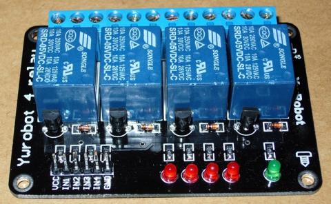
Relays work on electromagnetism, When the Relay coil is energized it acts like a magnet and changes the position of a switch. The circuit which powers the coil is completely isolated from the part which switches ON/OFF, This provides electrical isolation. This is the reason we can control a relay using 5V's from an arduino and the other end of it could be running an 230V appliance, the 230V end is completely isolated from the 5V arduino circuitry.
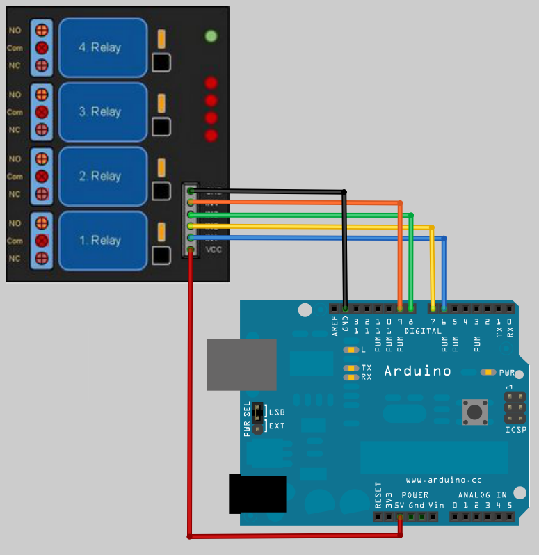
To connect the 4 Relay board to an Arduino is very easy and allows you to turn on and off an wide range of devices, both AC and DC. The first to connections are the ground and power pins, You need to connect the Arduino +5v to the 4 Relay board VCC pin and the Arduino ground to the 4 Relay board GND pin. Then it’s a only a matter of just connecting the communication pins, labeled IN1, IN2, IN3 and IN4, two 4 data pinson the Arduino.In the example code below we used Arduino pins 7, 8 , 9, 10. Its a good idea to avoid using Data pins 0 and 1 as they are used by the Arduino for serial communication and can cause problems when uploading code to the Arduino.
The default state of the relay when the power is off for COMM (power) to be connected to NC (normally closed), this is the equivalent of setting the 4 Relay boards IN pin to HIGH (has +5v sent to it) It is a safety feature to notuse the NC connector in-case you Arduino looses power it will automatically turns off all the devices connected to the relay. When you have something connected to the relays NO (Normally Open) connector and you set the corresponding IN pin to LOW (0v), power will flow in from the COMM connector and out of the NO connectorpowering your device..
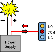
Above: Example of connecting power and lights to a relays COM and NO connectors.
Below: Connecting to the Arduino.
|
// Basic 4 Realy board connection // Each relay is turned on for 2 seconds and then off. // You can here them click as there state changes from off to on and on to // off. // You will also see the corresponding Red LED on the 4 Relay board // light up when the relay is on.
// define names for the 4 Digital pins On the Arduino // These data pins link to 4 Relay board pins IN1, IN2, IN3, IN4 #define RELAY1 6 #define RELAY2 7 #define RELAY3 8 #define RELAY4 9
void setup() { // Initialise the Arduino data pins for OUTPUT pinMode(RELAY1, OUTPUT); pinMode(RELAY2, OUTPUT); pinMode(RELAY3, OUTPUT); pinMode(RELAY4, OUTPUT); }
void loop() { digitalWrite(RELAY1,LOW); // Turns ON Relays 1 delay(2000); // Wait 2 seconds digitalWrite(RELAY1,HIGH); // Turns Relay Off
digitalWrite(RELAY2,LOW); // Turns ON Relays 2 delay(2000); // Wait 2 seconds digitalWrite(RELAY2,HIGH); // Turns Relay Off
digitalWrite(RELAY3,LOW); // Turns ON Relays 3 delay(2000); // Wait 2 seconds digitalWrite(RELAY3,HIGH); // Turns Relay Off
digitalWrite(RELAY4,LOW); // Turns ON Relays 4 delay(2000); // Wait 2 seconds digitalWrite(RELAY4,HIGH); // Turns Relay Off }
|