LCD 1602 pinout and Interface
The LCD pins are numbered from 1- 16 , look behind the LCD to see the numbering.
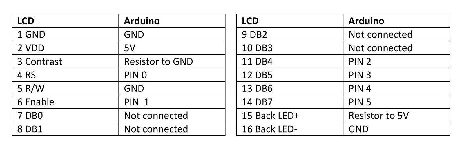
The table below explains how to connect the LCD pins to the Arduino.
In the case where the LCD is powered with the Arduino by the 5V USB cable, selecting the contrast resistor to be 2K ohm and the back LED resistor to be 100 ohm is a good start. Alternatively, a 5K potentiometer can be used to adjust the contrast for vest viewing.
NOTE: We now supply a variable resistor ( potentiometer ) which replaces the resistor seen in diagram. Its much easier to fine tune LCD contrast with a variable resistor.
Wiring with Arduino
Follow the above table and circuit diagram in Fig 1, and wire up the LCD using the wires provided.
Color coding:
|
Wire Color |
Description |
| RED | VCC of +5V |
| BLACK | Ground |
| Other colors | Data and signal lines |

Fig 1. LCD to Arduino interfacing circuit
Code
In this example we use the Arduino pins 0,1,2,3,4 & 5 for connectivity to the LCD pins 4,6, 11,12,13 & 14, respectively (see table 1). Therefore in Arduino code, we initialise the lcd() as follows:
LiquidCrystal lcd(0, 1, 2, 3, 4, 5);
This code segment tells the Arduino how the LCD is connected to it.
Download this LCD test code and open it in the installed Arduino Development Environment,
This code example will test the LCD and display a message.