In this tutorial we are going to take the basic concepts from the last two tutorials and create an Arduino based automatic garden watering system.
The system will be controlled using the Processing language. Below is the flow diagram of the system layout
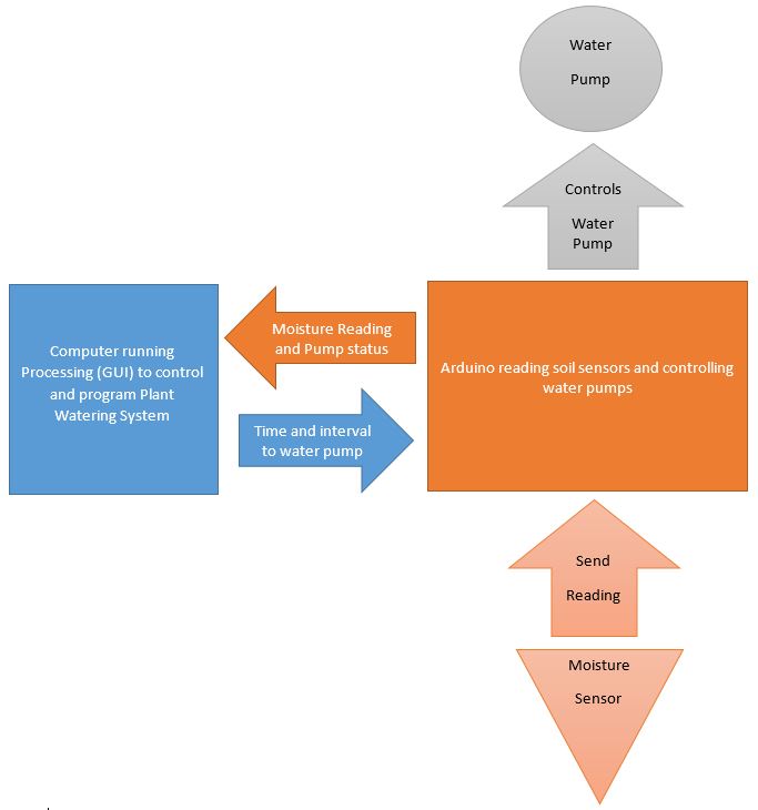
In the setup Arduino will work together with Processing to create an automatic plant watering system. Arduino will be used to read soil moisture data from soil and send the data to Processing. Processing will use that data to determine if soil is dry and requires water. Processing will then tell Arduino to turn on the water pump for a specific period.
We will use the GUI in processing to design different options on how we control the water pump based on the moisture data.
There are couple of GUI designers available for Processing, but we will be using G4P GUI that’s come bundled with Processing 3. It’s very simple to learn and work with.
Setup:
The Automatic Plant Watering system will have two soil sensors and two water pumps. Each soil sensor will determine which water pump water is activated to water the soil.
Summary of Steps:
- Installing latest version of Processing and Arduino IDE
- Installed/update to latest G4P library and Tool in Processing
- Design the GUI
- Wire up the components together
- Write the code
- Test
- Optional Changes
- Arduino
- Water Pumps (2 for this project)
- Soil Moistures (2 for this project)
- NPN Transistors OR Single Relays (2 for this project)
- Water hose (for connecting the water pump) - 2 pieces for each pump
- Wires for connections
- Power supply for water pump - battery or DC power source. ( make sure the voltage is correct for your pumps requirements)
- Water source - tank to supply water to pimps
- Pot plants - to measure soil moisture
- PC with Arduino and Processing IDE loaded with latest version and required libraries.
Installing latest version of Processing and Arduino
Make sure that either you have updated both Arduino and Processing IDE or have installed the latest version available.
For Arduino IDE check https://www.arduino.cc/en/main/software
For Processing IDE check https://processing.org/download/
Installed/update to latest G4P library and Tool in Processing
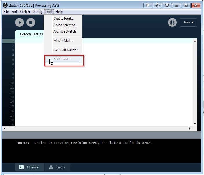
- To update Library in Processing IDE. C lick Tools -> Add Tool
2. On the Contribution Manager window, Click on the Library Tab. Scroll down to G4P and make sure that its updated.
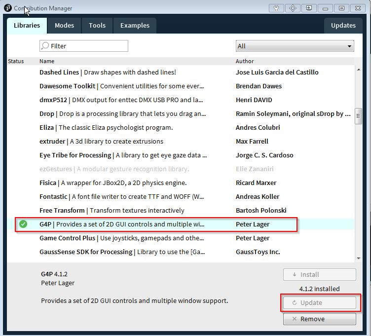
3.
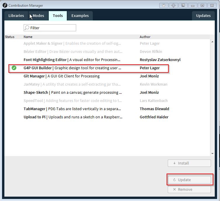
After the update is completed. Click on the Tools Tab and scroll to G4P tools and update that too.
Design the GUI
If you are new to G4P GUI Building tool. I strongly suggest watching some of the tutorial video to get a handle on it. Below is link that provides some of the introductory videos for starters
http://lagers.org.uk/g4ptool/v1-introduction.html
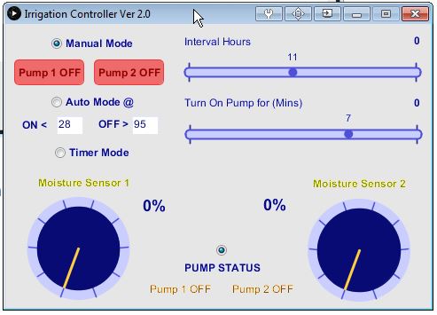
The GUI above has three mode of function;
- Manual Mode – users can turn water pump 1 and 2 ON and OFF manually
- Auto Mode – users can set at what specific readings from the soil sensor will both the both the pumps will turn ON and OFF. E.g Turn pump ON when soil moisture is lesss than (<) 28 % and Turn pump OFF when soil moisture is greater then (>) 95 %.
- Timer Mode - users use the sliders to set the period time Pumps will be ON for and at what interval. E.g. on every 2 hours turn pumps ON for 5 mins.
The two dials at the bottom of the GUI display real time soil moisture reading and Pump Status (if the pumps are turned ON or OFF).
The indicator light (Blinking) in the middle shows Processing is communicating correctly with Arduino. If the light is not blinking, Arduino might have stopped or is not communicating to Processing.
Wire up the components together
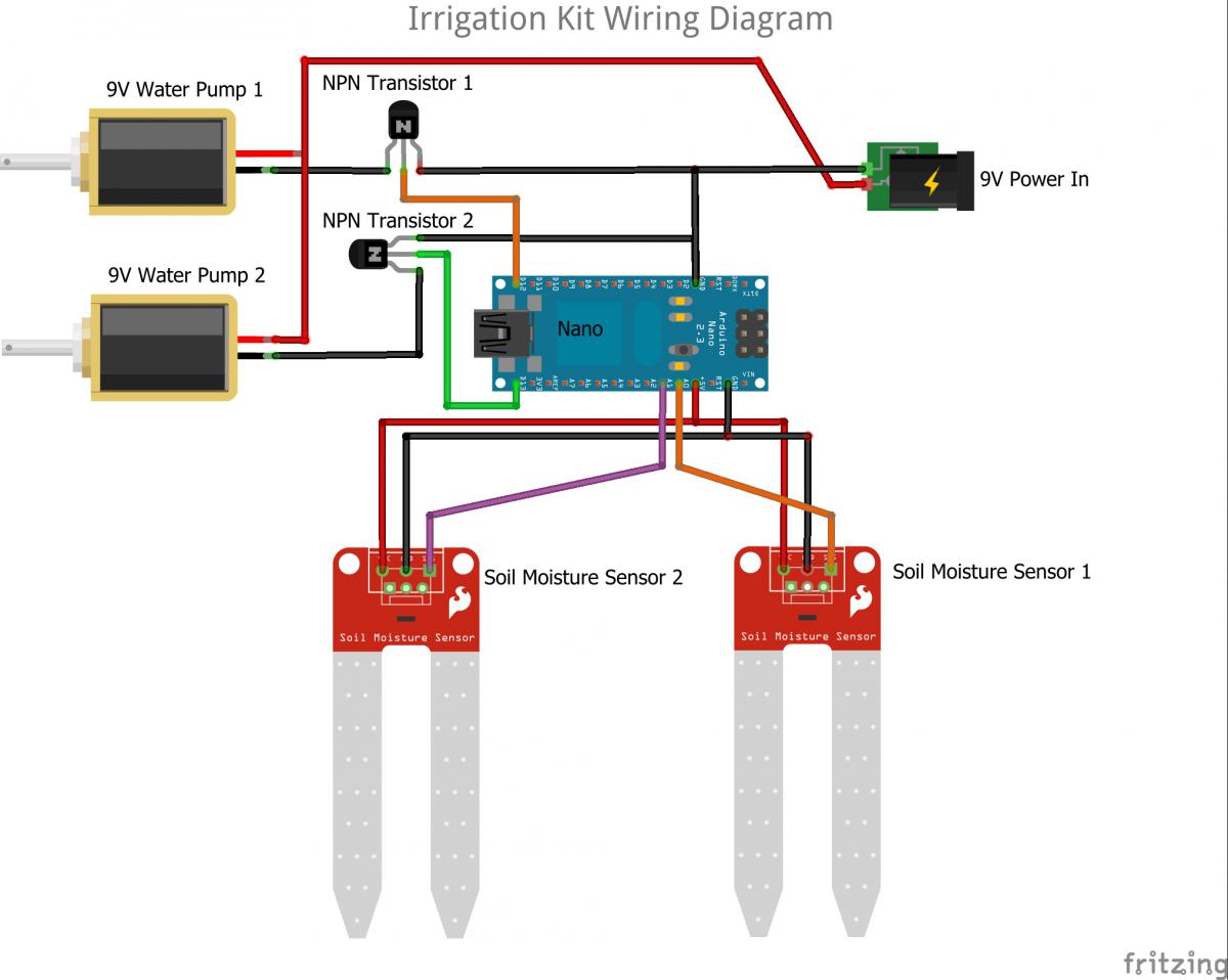
Diagram 1 using NPN transistor as switch
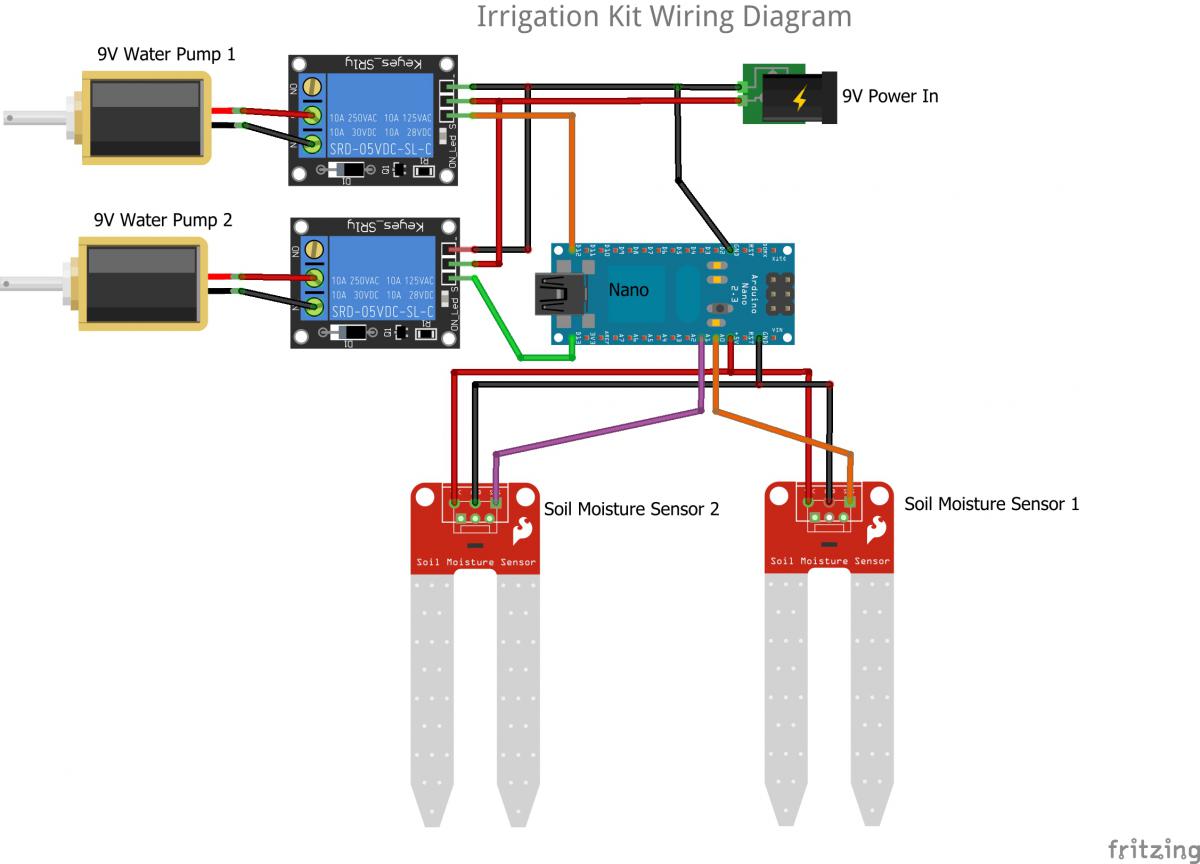
Diagram 2 using Relays as switch
The wiring shows water pump are power by 9V power separately. Arduino is powered through USB at this stage, but if you wish you can use the same 9V to power Arduino also with few changes.
Write the code
Arduino Code
/* Irrigation ProjectThis project has two parts; Arduino board communicates with Processing
Arduino is connected with two soil sensors and two water pumps. Water pump turns ON and OFF
base on the reading from the soil sensors.
Processing is used to control and config the setting on arduinoArduino sends sensor reading and pump status to ProcessingProcessing GUI displays the sensor reading and send commands back to Arduino to control the pump*/// Assign the soil sensor and pump variables// Soil Sensor 1 input at Analog PIN A0int Sensor1 = 0;// Soil Sensor 2 input at Analog PIN A1int Sensor2 = 1;// Pump 1 ON/OFF control on Digital Pin 13
int Pump1 = 13;// Pump 2 ON/OFF control on Digital Pin 12int Pump2 = 12;// variable to hold value from moisture sensor 1int Sensor1Value = 0;// variable to hold value from moisture sensor 2int Sensor2Value = 0;// variable to hold pump1 state : 0 = OFF and 1 = ONint Pump1State = 0;// variable to hold pump2 state : 2 = OFF and 3 = ONint Pump2State = 2;
//variable to hold data from processing - this is what processing is sents to arduino - command signalsint processingData;void setup() {//set the buad rate for serial communication
//make sure that its the same buad rate set on ProcessingSerial.begin(9600);
//assign the pin as output for pump pins 12 and 13pinMode(Pump1, OUTPUT);pinMode(Pump2, OUTPUT);
//set initial set of both pumps to OFF and assign it to the pump state variable
digitalWrite(Pump1, LOW);
digitalWrite(Pump2, LOW);
Pump1State = 0; //OFF
Pump2State = 2; //OFF
// send a byte to establish contact until receiver respondsestablishContact();
}void loop() {//get the reading from the sensors and assigns to variablesgetSensorReading();
delay(100);
//send to processingdataExchange();}//gets the reading from the sensors and assigns them to the variablevoid getSensorReading() {Sensor1Value = analogRead(Sensor1);
Sensor2Value = analogRead(Sensor2);
Sensor1Value = Sensor1Value / 10;Sensor2Value = Sensor2Value / 10;}//turns pumps ON and OFFvoid pumpSwitch(int pumpState) {//turn Pump 1 ON and set Pump1 State to 0
if (pumpState == 0) {
digitalWrite(Pump1, LOW);
Pump1State = 0;
}
//turn Pump 1 OFF and set Pump1 State to 1if (pumpState == 1) {digitalWrite(Pump1, HIGH);Pump1State = 1;}//turn Pump 2 ON and set Pump2 State to 2if (pumpState == 2) {digitalWrite(Pump2, LOW);Pump2State = 2;}//turn Pump 2 OFF and set Pump2 State to 3if (pumpState == 3) {digitalWrite(Pump2, HIGH);Pump2State = 3;}}//send the data to Processingvoid sendToProcessing () {Serial.print(Sensor1Value);Serial.print("*");
Serial.print(Sensor2Value);Serial.print("^");
Serial.print(Pump1State);Serial.print("$");Serial.print(Pump2State);
Serial.print("%");
//send a carriage returnSerial.println();}//function to do exchange of data between arduino and processinvoid dataExchange () {// If data is available to read,
if (Serial.available() > 0) {// read it and store it in valprocessingData = Serial.read();//what to do when data from processing is received.
if (processingData == '0') //if we get a 0{//turn OFF pump 1 when it get its signal from processing
pumpSwitch(0);}if (processingData == '1') //if we get a 1
{
//turn ON pump 1 when it get its signal from processingpumpSwitch(1);
}if (processingData == '2') //if we get a 2{//turn OFF pump 2 when it get its signal from processingpumpSwitch(2);
}if (processingData == '3') //if we get a 3{
//turn ON pump 2 when it get its signal from processingpumpSwitch(3);}delay(50);}else {//send sensor reading and pump status to ProcessingsendToProcessing ();delay(50);}}//function to establish contact between arduino and processingvoid establishContact() {while (Serial.available() <= 0) {Serial.println("A"); // send a capital Adelay(100);}}
The above code first establish the connection with Processing. It takes soil sensor data and Pump state and sends it to Processing and receives and executes commands sent by Processing to turn ON and OFF the pumps.
Processing Code
Main Code
/* Irrigation Project
* This is the Processing end that talks to Arduino. THis receives the soil sensor reading
* and send commands to control the pump accroding the the user setting.
* Processing send one digit int to Arduno to control the pump. Arduino identifies
* what data sent means and act on turning the Pump ON or OFF accordingly.
* User data is saved on a seperate txt file and is saved when user does any changes to
* setting and is retrived back when the program starts.
* Note that the confiqfile.txt file that saves and retrives user data needs to have dummy data to start with.
* (the above can be avoided by using checking if null data is pulling in and then setting some default values).
* GUI for this project is built using G4P tool. You will need the updated library and Tool installed.
* For testing purpose the auto timer sliders are can be set to Mins and Sec instead of Hours and Min. This need to be
* changed on the gui tab under two functions;
* 1. public void sliderIntervalHour_change1
* 2. public void sliderPeriodAction_change1
*/
//inistate all the needed librarys
// Need G4P library
//library for GUI used by G4P tool Builder
import g4p_controls.*;
//library for serial communication
import processing.serial.*;
//library for changing GUI fonts
import java.awt.Font;
// Create object from Serial class
Serial myPort;
// variable to store sensor1 reading
String Sensor1;
// variable to store sensor1 reading
String Sensor2;
// variable to store pump 1 state reading
String Pump1State;
// variable to store pump 2 state reading
String Pump2State;
// variable to hold that data that will be sent to arduino
Integer processingData;
// since we're doing serial handshaking,
// we need to check if we've heard from the microcontroller
boolean firstContact = false;
// variable to hold the handshake connection check
String handShake;
//assign variable for interval hour and period of action when in AutoMode
int intervalHour = 0;
int periodAction = 0;
int intPeriodBegin = 0;
int intPeriodTime = 0;
int intPeriodDuration = 0;
boolean PeriodCheck = false;
int intIntervalBegin = 0;
int intIntervalTime = 0;
int intIntervalDuration = 0;
boolean IntervalCheck = false;
//assign variable to capture data read and write from file - used to save user config data
String[] configData;
//code to run at setup
public void setup() {
// Open whatever port is the one you're using.
String portName = Serial.list()[0]; //change the 0 to a 1 or 2 etc. to match your port
myPort = new Serial(this, portName, 9600); //make sure baud rate is same as what is set in arduino
// this will fill in buffer till we see the last character that we are looking for (that's coming from srduino).
myPort.bufferUntil('\n');
//sets up the screen resolution and GUI
size(480, 320, JAVA2D);
createGUI();
customGUI();
//increase the font size in sensor reading % label
lblSensor1ReadingP.setFont(new Font("Arial", Font.PLAIN, 18));
lblSensor2ReadingP.setFont(new Font("Arial", Font.PLAIN, 18));
//loads the user data from file
loadData();
//on start reset pumps to OFF
pumpOFF();
}
public void draw() {
background(230);
}
//save config data to file
public void saveData() {
//assign user setting to the variable array
configData[0] = str(intervalHour);
configData[1] = str(periodAction);
configData[2] = str(optAutoMode.isSelected());
configData[3] = str(optTimerMode.isSelected());
configData[4] = txtAutoModeON.getText();
configData[5] = txtAutoModeOFF.getText();
configData[6] = str(optManualMode.isSelected());
//save the variable to a file
saveStrings("configFile.txt", configData);
}
//load congif data from file
public void loadData() {
//read config data from file to variable array
configData = loadStrings("configFile.txt");
//for testing purpose
println(configData[0]);
println(configData[1]);
println(configData[2]);
println(configData[3]);
println(configData[4]);
println(configData[5]);
println(configData[6]);
//assign the variable to user seting field
txtAutoModeON.setText(configData[4]);
txtAutoModeOFF.setText(configData[5]);
intervalHour = int(configData[0]);
sliderIntervalHour.setValue(intervalHour);
periodAction = int(configData[1]);
sliderPeriodAction.setValue(periodAction);
boolean blnAutoMode = boolean(configData[2]);
if (blnAutoMode == true) {
optAutoMode.setSelected(true);
//for testing purpose
println("Auto Mode Selected");
}
boolean blnTimerMode = boolean(configData[3]);
if (blnTimerMode == true) {
optTimerMode.setSelected(true);
//for testing purpose
println("Timer Mode Selected");
}
boolean blnManualMode = boolean(configData[6]);
if (blnManualMode == true) {
optManualMode.setSelected(true);
//for testing purpose
println("Manual Mode Selected");
}
}
void serialEvent( Serial myPort) {
//put the incoming data into a String -
//the '\n' is our end delimiter indicating the end of a complete packet
//store them in temp Variable to rule out any null data coming through
String Sensor1temp = myPort.readStringUntil('*');
String Sensor2temp = myPort.readStringUntil('^');
String Pump1Statetemp = myPort.readStringUntil('$');
String Pump2Statetemp = myPort.readStringUntil('%');
handShake = myPort.readStringUntil('\n');
//make sure our data isn't empty before continuing
//if data avaiable is not null then store in proper variables and replace the special charaters with blank
if (Sensor1temp != null) {
Sensor1 = Sensor1temp.replaceFirst("\\*", "");
}
if (Sensor2temp != null) {
Sensor2 = Sensor2temp.replaceFirst("\\^", "");
}
if (Pump1Statetemp != null) {
Pump1State = Pump1Statetemp.replaceFirst("\\$", "");
}
if (Pump2Statetemp != null) {
Pump2State = Pump2Statetemp.replaceFirst("\\%", "");
}
//make sure our data isn't empty before continuing
if (handShake != null) {
//trim whitespace and formatting characters (like carriage return)
handShake = trim(handShake);
println("handShake " + handShake);
//look for our 'A' string to start the handshake
//if it's there, clear the buffer, and send a request for data
if (firstContact == false) {
if (handShake.equals("A")) {
myPort.clear();
firstContact = true;
myPort.write("A");
println("contact");
}
} else { //if we've already established contact, keep getting and parsing data
println(Sensor1);
println(Sensor2);
println(Pump1State);
println(Pump2State);
println("Sensor Read " + millis());
//you can also program other ways of controlling pump here like example below
//i.e. by click the mouse will turn the pump ON
//if (mousePressed == true)
//{ //if we clicked in the window
// myPort.write('1'); //send a 1
// println("1");
//}
//this is just an app indicator to show that the app is running by toggling option button
if (optAppRunning.isSelected() == true) {
optAppRunning.setSelected(false);
} else
{
optAppRunning.setSelected(true);
}
//calls the function that does all the processing
Process();
// when you've parsed the data you have, ask for more:
myPort.write("A");
}
}
}
// to reset pumps...turn both pumps OFF
public void pumpOFF() {
//turn Pump 1 and pump 2 OFF
myPort.write('0');
delay(300);
lblPump1Status.setText("Pump 1 OFF");
btnPump1.setText("Pump 1 OFF");
btnPump1.setTextBold();
btnPump1.setLocalColorScheme(GCScheme.RED_SCHEME);
println("PUMP 1 OFF");
myPort.write('2');
delay(300);
lblPump2Status.setText("Pump 2 OFF");
btnPump2.setText("Pump 2 OFF");
btnPump2.setTextBold();
btnPump2.setLocalColorScheme(GCScheme.RED_SCHEME);
println("PUMP 2 OFF");
}
public void Process() {
//sets the value from the moisture sensor to the dial display
if (Sensor1 != null) {
knob1.setValue(float(Sensor1));
//display the reading as percentage - using contrain to keep the value between 0-100
lblSensor1ReadingP.setText(constrain(int(Sensor1), 0, 100) + " %");
}
if (Sensor2 != null) {
//sets the value from the moisture sensor to the dial display
knob2.setValue(float(Sensor2));
//display the reading - using contrain to keep the value between 0-100
lblSensor2ReadingP.setText(constrain(int(Sensor2), 0, 100) + " %");
}
//for testing purpose
//print("Interval Hour: ");
//println(intervalHour);
//Start Timer if Timer Mode selected else keep PUMP OFF
if (optTimerMode.isSelected() == true) {
//check if intervalHour is not 0 when timer starts
if (intervalHour == 0) {
InterHourTimer.stop();
IntervalCheck = false;
} else {
InterHourTimer.start();
}
//countdown
if (PeriodCheck == true) {
intPeriodTime = intPeriodDuration - (millis() - intPeriodBegin);
lblPeriodTimer.setText(str(intPeriodTime /1000 ));
}
if (IntervalCheck == true) {
intIntervalTime = intIntervalDuration - (millis() - intIntervalBegin);
lblIntervalTimer.setText(str(intIntervalTime / 1000 ));
}
//for testing purpose
println("Timer Mode ON " + millis());
} else {
lblPeriodTimer.setText("0");
lblIntervalTimer.setText("0");
}
//Check if Auto Mode is selected - start the Auto Mode else turn PUMP OFF
if (optAutoMode.isSelected() == true) {
//check at what moisture rating should PUMP start
//Start PUMP 1 if moisture sensor 1 match the set mositure level
if (Sensor1 != null) {
if (int(Sensor1) < int(txtAutoModeON.getText()) ) {
myPort.write('1');
lblPump1Status.setText("Pump 1 ON");
//for test purpose
println("PUMP 1 ON");
println(millis());
} else {
//Stop PUMP 1 when moisture reading is > what set in OFF > by the user
if (int(Sensor1) > int(txtAutoModeOFF.getText())) {
myPort.write('0');
lblPump1Status.setText("Pump 1 OFF");
//for test purpose
println("PUMP 1 OFF");
}
}
}
//Start PUMP 2 if moisture sensor 1 match the set mositure level
if (Sensor2 != null) {
if (int(Sensor2) < int(txtAutoModeON.getText())) {
myPort.write('3');
lblPump2Status.setText("Pump 2 ON");
//for test purpose
println("PUMP 2 ON");
} else {
//Stop PUMP 2 when moisture reading is > what set in OFF > by the user
if (int(Sensor2) > int(txtAutoModeOFF.getText())) {
myPort.write('2');
lblPump2Status.setText("Pump 2 OFF");
//for test purpose
println("PUMP 2 OFF");
}
}
}
//for testing purpose
println("Auto Mode ON " + millis());
}
}
// Use this method to add additional statements
// to customise the GUI controls
public void customGUI() {
}
The above code is two part code. Main code as show above and the GUI code that is generated by the G4P tool. Download the attached code files that included. All the code file have comments thats explains the purpose.
Arduino and Processing Code file - click here to download the files.
Video of prototype:
Optional Changes
Bluetooh communication
Below is the wiring for connecting bluetooth module for wireless communication from Processing
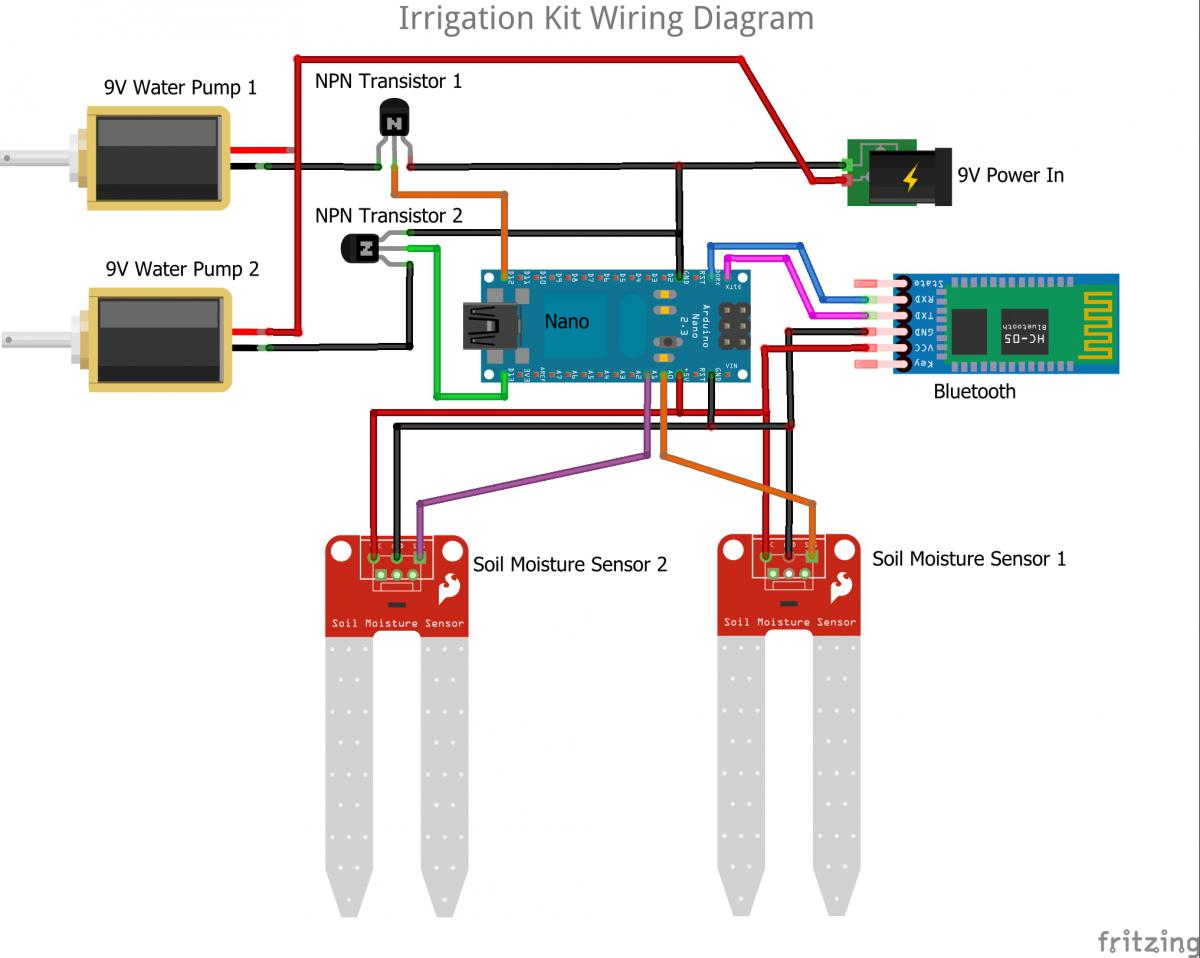
Diagram 1 using NPN transistor as switch with BT Module for communication
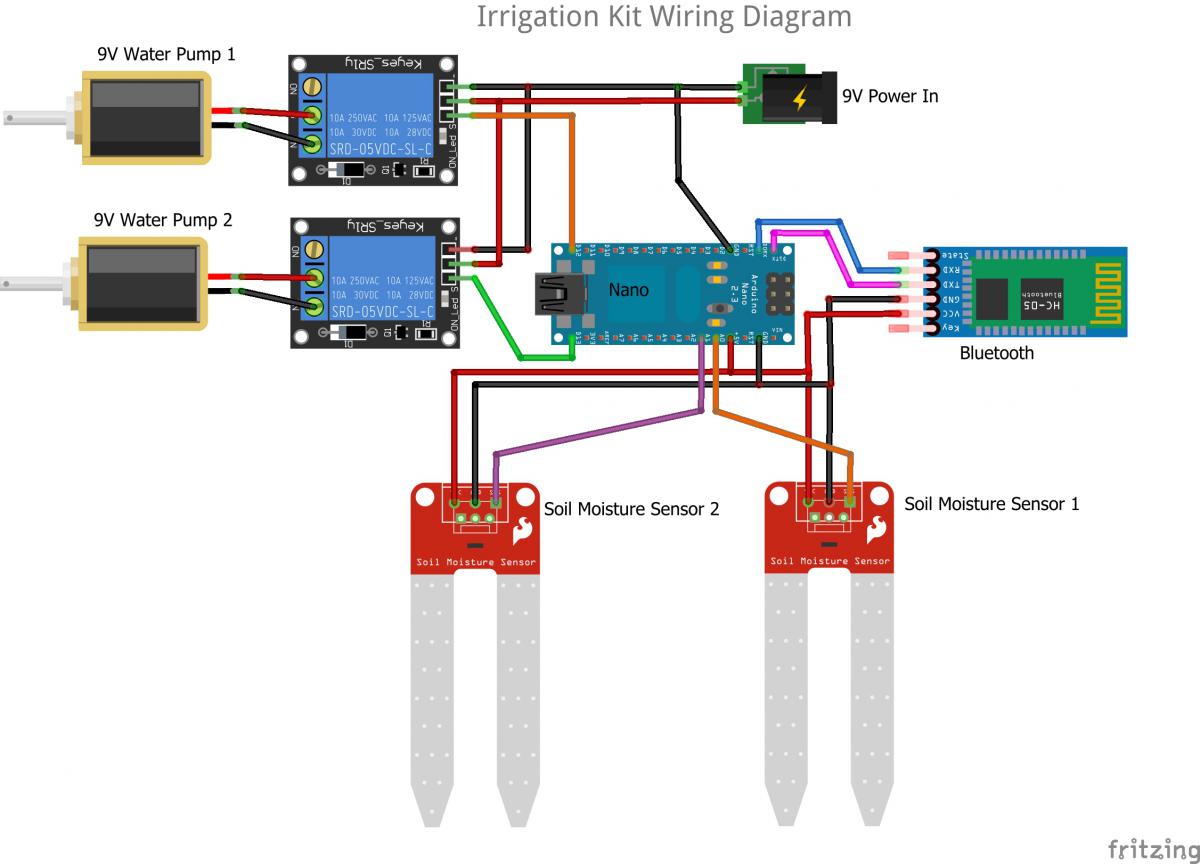
Diagram 2 using Relay as swith with BT module for communication