Flow Meter Working Principle
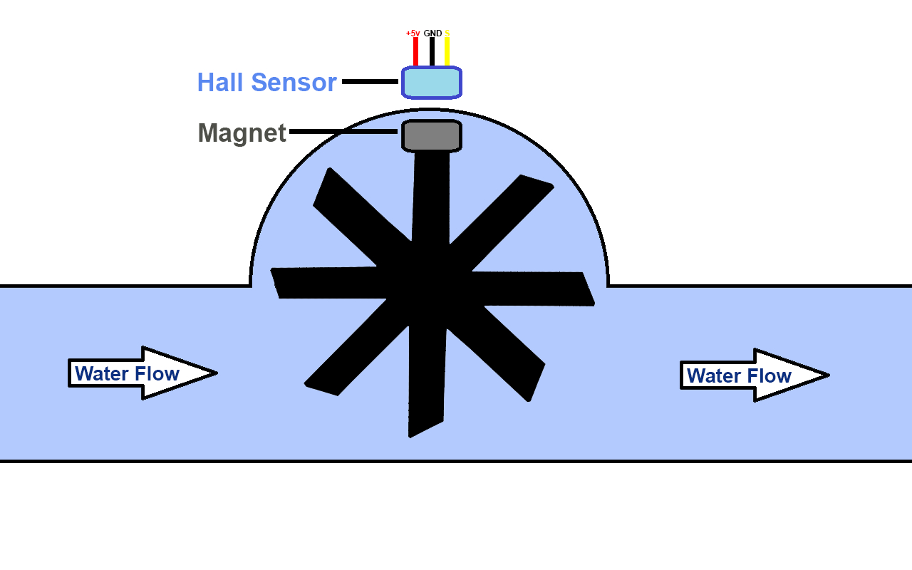
As the name suggests, flow meter works on the principle of Hall Effect. A turbine wheel is present inside the body with a magnet embedded on one edge of the turbine wheel.
When fluid flows through, the wheel moves and with the rotation of the wheel, the magnet creates flux on the sensory end. With each magnetic input, a pulse is generated on the Hall Sensor’s
output.
In order to process this information, the sensor is connected with an Arduino board. The digital pulses of Hall Sensor are detected on Arduino Board. The number of pulses is measured and
processed for calculation of flow rate.
There are various methods of displaying this information. In this case, the information is displayed on an LCD and on the Serial Monitor of Arduino.
The flow meter is discussed in this article is based on YF-S201 Hall Sensor. It is capable of measuring 1-30 Liters/Minute with a tolerance of ±5%.The relation between Flow rate and Pulses is
Q =F ÷ 7.5
Where,
Q = Flow Rate (Liters/Minute)
F = Frequency of Hall Sensor’s Pulses
For example, if the Hall Sensor produces 75 pulses, it means the flow rate is 10 Liters/Minute.
Similarly, if the Hall Sensor produces 150 pulses, it means the flow rate is 20 Liters/Minute.

Applications of Flow Meter:
Flow meters have various applications, and they are used in multiple industries. Some of the significant application of flow meters are
- Water regulation in bottle filling plants
- Water flow sensing in water metering systems
- Wastewater measurement
- Water regulation in agriculture, oil and chemical industry
- Lubrication oil regulation in machines
Flow Meter Design and Development
The flow meter design and development involves hardware and software, let’s see how it is developed.
Arduino Coding
The very first step in flow meter development is writing Arduino code. As the Arduino UNO connected with Hall Sensor,
needs to be programmed for communication, a sketch code has to be compiled using Arduino IDE software.
In order to display real-time results on the computer, the Serial Monitor on the computer can be used. Alternatively, the results can be seen on LCD.
#include <LiquidCrystal.h>
LiquidCrystal lcd(10, 9, 8, 7, 6, 5);
unsigned char flow_sensor_pin = 2;
unsigned int flow_per_min;
unsigned long current_time;
unsigned long cloop_time;
volatile int sensor_pulses;


void setup()
{
  Serial.begin(9600);
  sei();
  lcd.begin(16, 2);
  lcd.clear();
  lcd.setCursor(0, 0);
  lcd.print(" Flow Meter ");

  pinMode(flow_sensor_pin, INPUT);
  digitalWrite(flow_sensor_pin, HIGH);
  attachInterrupt(0, pulses_measure, RISING);

  current_time = millis();
  cloop_time = current_time;
}

void loop ()
{
  current_time = millis();
  if (current_time >= (cloop_time + 1000))
  {
    cloop_time = current_time;
    flow_per_min = (sensor_pulses / 7.5);
    sensor_pulses = 0;

    Serial.print(flow_per_min, DEC);
    Serial.println(" L/MIN");

    lcd.setCursor(0, 1);
    lcd.print(" ");
    lcd.setCursor(0, 1);
    lcd.print(" Flow:");
    lcd.print(flow_per_min, DEC);
    lcd.print(" L/MIN");
    delay(100);
  }
}

void pulses_measure ()
{
  sensor_pulses++;
}
Hardware
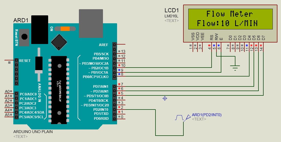
After finalization of design, the next step is to develop the hardware. Just as shown in the schematic diagram, the flow sensor is connected with Arduino Board using jumper wires.
Hall Sensor has 3 pins, two pins are for power, and one pin is for output. The Sensor’s output pin is connected with Arduino Board Pin 2. The pin 2 on Arduino Board is capable of handling interrupt function which is necessary for measuring Hall Sensor’s pulses.
The output signal (Yellow) of flow sensor needs to be pulled up. A pull up resistor can be connected between signal and +5v pin. Alternatively, the signal pin can be pulled up inside the code.
The Red pin can be connected on +5 and the Black pin on GND on Arduino Board. Hall Sensor consumes only 15-20mA which safe to be powered directly from Arduino.
The LCD is connected on pin 5-10 on Arduino Board. It can be changed if necessary.
After the hardware design is connected as shown in the schematic, make sure, the sensor is connected with water running pipes and slowly increase the flow. The flow rate on LCD must increase accordingly.
The Arduino boards takes several readings and then presents a precise value. According to this code, the flow rate updates every 100 milliseconds.
What’s next?
If you have followed all instructions and successfully developed a flow meter, you can add more features to it.
Smart flow meters used in industry are equipped with alarms, if the flow rate rises above a certain level, the microcontroller triggers the alarm. Similarly, buzzer or LED’s can be connected with Arduino Board and triggered above a specific value.