The demand of automation is increasing day by day. A couple of years back, the automation of drives was very difficult due to the bad efficiencies of the components but after the invention of microcontrollers, it is very easy to control and automate the drives.
DC motors can be found anywhere. DC motor converts the electrical energy (direct current) into mechanical energy. The basic working principle of dc motor is that whenever a current carrying conductor is placed in a magnetic field, it experiences a mechanical force that has the tendency to move. If the direction of current is reversed then the rotation of motor will also reverse.
In default mode of operation, electric motors operate by the interaction of the magnetic field and the winding current to generate a force.
The speed of dc motor can be controller in many ways like we can add a variable resistor in series with the motor but we will control the speed of dc motor using the l298 motor controller by the PWM (pulse width modulation) method which is efficient than the other methods. Before studying the speed control of dc motor we will discuss about how the PWM method works.
How PWM Works
The pulse width modulation method is a very efficient method and is the most commonly used method. The PWM method drives the motor by applying a series of ON and OFF pulses. It varies the duty cycle by applying the ON or OFF time greater or lower while keeping the frequency constant. The pulse width modulation signal is a square signal which has a high frequency (more than 1 KHz). If we want to vary the power supplied then we have to vary the duty cycle of this square wave. Duty cycle is the fraction of time in which the signal was high. The duty cycle can be varied from 0% to 100%. PWM waves with different duty cycles are shown in the figure below.
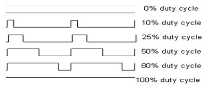
The formula for calculating the duty cycle of square wave is below.
%Duty Cycle = (TON / (TON + TOFF)) * 100
TON is the time in which the square wave will be on.
TOFF is the time in which the square wave will be off.
When the Control signal is given to the PWM controller then the PWM controller adjusts the duty cycle according to the control signal.
L298 Motor Controller
The L298 motor controller has the ability to control two DC motors at a time and it can be used with any micro-controller. It uses the L298 H Bridge IC which can give output current up to 2A. Due to its high current rating, we can control a heavy duty stepper Motor with it.
This module is not only designed to control the DC motor but we can also control the solenoids, relays and stepper motors.
The L298 motor controller is a low cost but it moves the DC motor in
-
Clockwise direction
-
Anti-clockwise direction
-
Stall
Click here to read about L298 Motor Controller in detail.
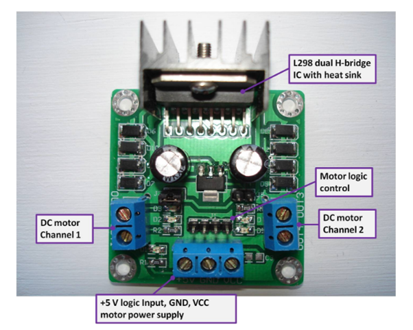
L298 Motor Controller Pin out
DC Motor Channel 1: Connect the first motor here.
DC Motor Channel 2: Connect the second motor here.
Motor logic control: It consists of four pins IN1, IN2, IN3, and IN4. The IN1 and IN2 are responsible for the control of DC Motor Channel 1 while the IN3 and IN4 are responsible for the control of DC Motor Channel 2.
+5 V: Connect the 5 v of Arduino.
VCC: Connect the positive of power supply. The voltage of power supply should be from 5 to 35v.
GND: Ground will be shared with the gnd of Arduino and the negative of power supply.
The VCC in the motor controller will drive the motors while the +5 V will power the electronics on the controller.
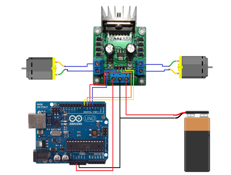
Controlling Two DC Motors with L298 Motor Controller
In this example we are going to control the DC motor using the L298 motor controller. This motor controller can operate in three modes depending on the connection of two jumper wires J3 and J5.
Mode 1: jumper J3 and J5 open circuit
In this mode, the VCC will be the power source for the motor which can supply voltage from 4 to 35V. The +5 v terminal will be input which we will give through the micro-controller.
Mode 2: jumper J3 short circuit, J5 open circuit
In this mode, the VCC will be the power source for the motor which can supply voltage from 7 to 35V. The terminal +5 V will be an output through which we can power microcontrollers.
Mode 3: jumper J3 open circuit, J5 short circuit
In this mode, the VCC will be the power source for the motor which can supply voltage from 7 to 35V. When the supply voltage is connected, the LED D1 is on. The terminal +5 V will be an output, but its voltage will be equal to the voltage of VCC.
Click here to know about modes in detail.
We will be using the mode 1. If you are using the motor which requires high voltage like servo motors then use the mode 2 or 3 because if you will use the mode 1 and will give the Arduino 5v then it will result in damage of the Arduino.
Components Required
-
2 DC Motors.
-
Arduino Uno (you can use any).
-
9V Power Supply.
-
L298 Motor Controller.
Connect the motors in the motor channel and power supply in the VCC and the GND. The GND is shared by the Arduino and the power supply. Connect the 5v of the Arduino to the +5v pin of the controller.
In this example we have used the Arduino digital pins which are 4, 5, 6, and 7. The reason for using these pins is that they are pwm pins.
Rotation Control
The rotation of dc motor is controlled by sending the high or low to the motor controller. For DC Motor Channel 1, high to IN1 and low to IN2 will move the motor in one direction and low to IN1 and high to IN2 will move it in other direction. Same is the case for DC Motor channel 2.

Code
//Controlling DC motors with l298 motor controller and Arduino.
int INPUT1 = 4; //initializing pwm pin 4 for controlling motor channel 1
int INPUT2 = 5; //initializing pwm pin 5 for controlling motor channel 1
int INPUT3 = 6; //initializing pwm pin 6 for controlling motor channel 2
int INPUT4 = 7; //initializing pwm pin 7 for controlling motor channel 2
void setup () {
pinMode (INPUT1, OUTPUT); //Enabling pin 4 as output
pinMode (INPUT2,OUTPUT); //Enabling pin 5 as output
pinMode (INPUT3,OUTPUT); //Enabling pin 6 as output
pinMode (INPUT4, OUTPUT); //Enabling pin 7 as output
}
void loop ()
{
// Rotates the Motor 1 clockwise
digitalWrite (INPUT1, HIGH); //This will rotate the motor 1 in clockwise direction.
digitalWrite (INPUT2, LOW);
delay (2000);
digitalWrite (INPUT1, HIGH);
digitalWrite (INPUT2, HIGH);
delay (500);
// Rotates the Motor 2 Clockwise
digitalWrite (INPUT3, HIGH); //This will rotate the motor 2 in clockwise direction.
digitalWrite (INPUT4, LOW);
delay (2000);
digitalWrite (INPUT3, HIGH);
digitalWrite (INPUT4, HIGH);
delay (500);
// Rotates the Motor 1 in the counter-clockwise direction
digitalWrite (INPUT1, LOW); //This will rotate the motor 1 in counter-clockwise direction.
digitalWrite (INPUT2, HIGH);
delay (2000);
digitalWrite (INPUT1, HIGH);
digitalWrite (INPUT2, HIGH);
delay (500); // Rotates Motor 2 in the counter-clockwise direction
digitalWrite (INPUT3, LOW); //This will rotate the motor 2 in counter clockwise direction.
digitalWrite (INPUT4, HIGH);
delay (2000);
digitalWrite (INPUT3, HIGH);
digitalWrite (INPUT4, HIGH);
delay (500);
}