Laser Scanning microscope works on the unerlying principle captured in below formula
Resolution (r) = λ/(2NA)
It states the Resolution of a microscope is
- Propotional to the Wavelength of light used to observer the specimen
- Inversely propotional to the numerical Aperture (NA)
Hence to improve the resolution ( ie make it see smaller objects ) we can do the following:
- Pick a smaller Wavelength
- Increase the Numerical Aperture
We use the former (reduction of Wavelength) to build the Laser Scanning Microscope.
We source the laser from DVD drives which has a wavelength of 650nm. The lower wavelength should give a better resolving power than traditional microscopes which uses light.
NOTE: The resolution can be improved by using Blue Ray (405nm) laser or going all the way to use an electron beam 2.5 picometer ( @ 200 KeV)
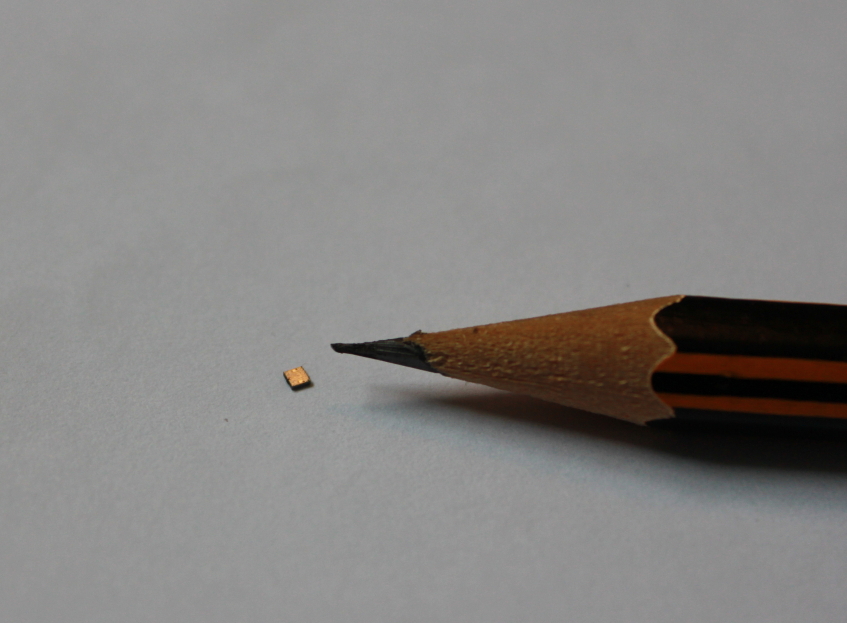
One of the specimens used was a Integrated Circuit which was decapped to extract the silicon at the heart of it.
Find below picture of one of the specimens used:
Below are some of the pictures taken from the Laser Scanning Microscope setup built using componets from a recycled DVD drive along with some electronics and software to render the image:
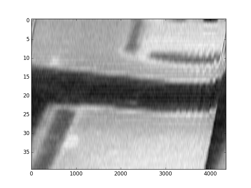
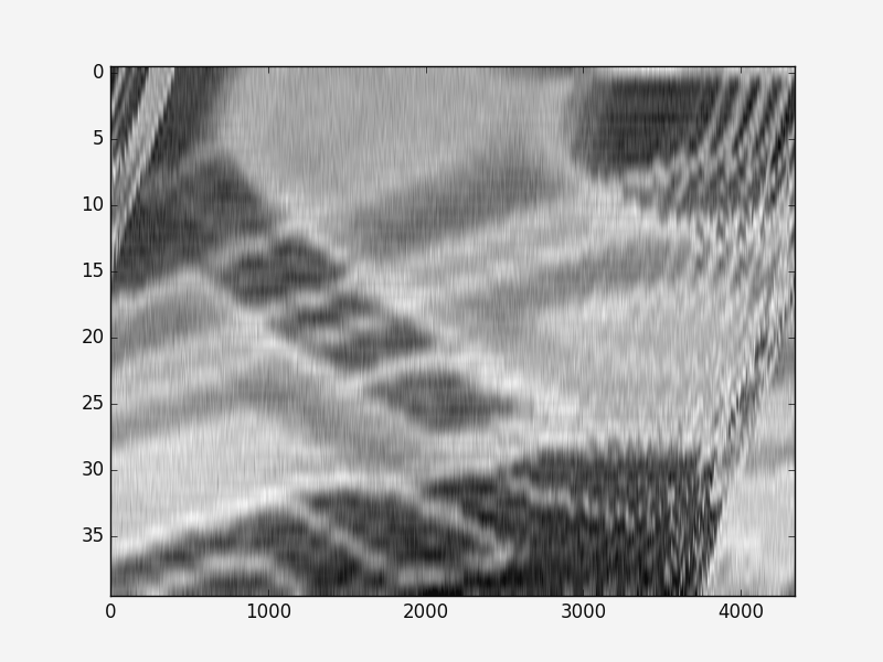
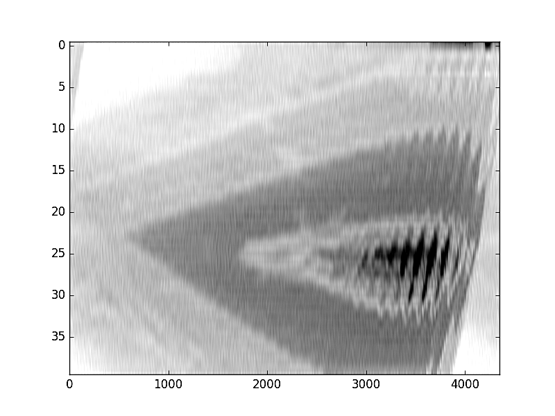
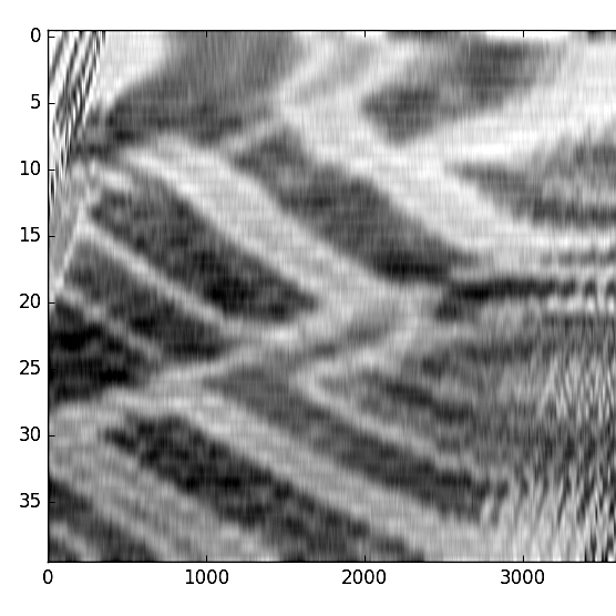
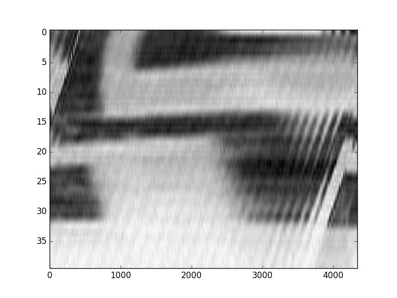
Fig: All the above images were rendered using the Laser Microscope setup detailed below
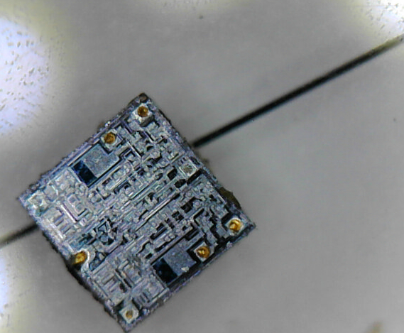
Fig: Picture of the decapped IC specimen taken with a USB microscope, The line in the background is 50 micron wide ( 0.05mm ). Compared to this the laser microscope is able to see much further and show the individual tracks in the Integrated circuit.
Inner workings of the Laser Scanning Microscope:
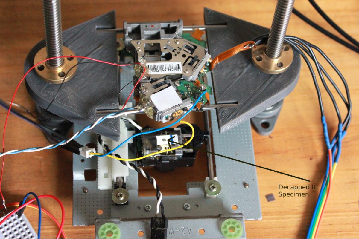
Fig: Closeup of the Specimen holder, you can see the photodiode wires blue& white and the rainbow cables used for the Horizontal Scan
The Laser Scanning Microscope has 2 important logical parts
1. The Scanning drive generator
This part is responsible for generating the Horizontal and Vertical axis scanning signals to move the Laser across the specimen
The Horizontal scan frequency in my setup is 1/40 times slower than the Vertical Scan, effectively giving 40 horizontal lines of scans for a specimen.
2. Picture generation using the reflected light from laser
The reflected light intensity contains the information of the visual detail of the Specimen, The reflected laser signal needs to be captured and the intensity
of the reflected light is to be converted to visual data to reconstruct the picture.
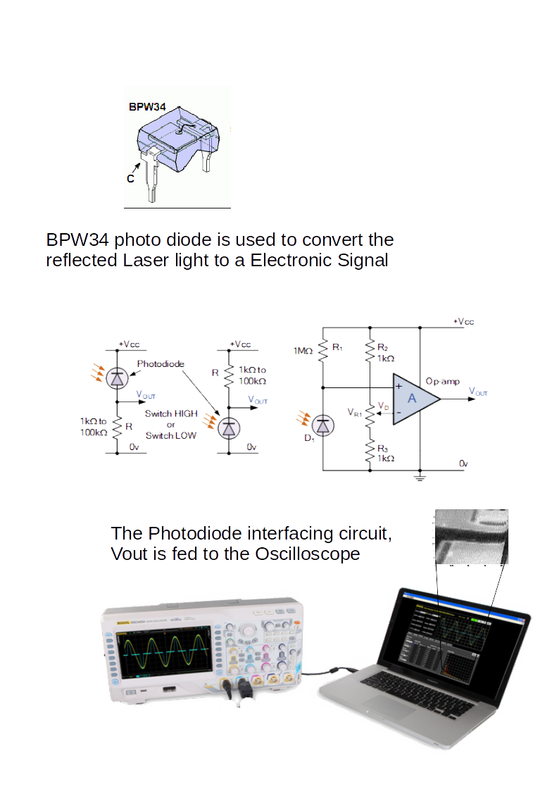
For capturing the light the setup uses a BPW34 photodiode which is setup in a potential divider circuit, the intensity of light recieved by the diode now is converted
as voltage variations which is captured by the Oscilloscope (RIGOL 1052E )
The Oscilloscope is connected to a PC which collects the sampled data and then converts the data into a black and white picture after doing some digital signal processing ( removing noise, getting the vertical sync etc )
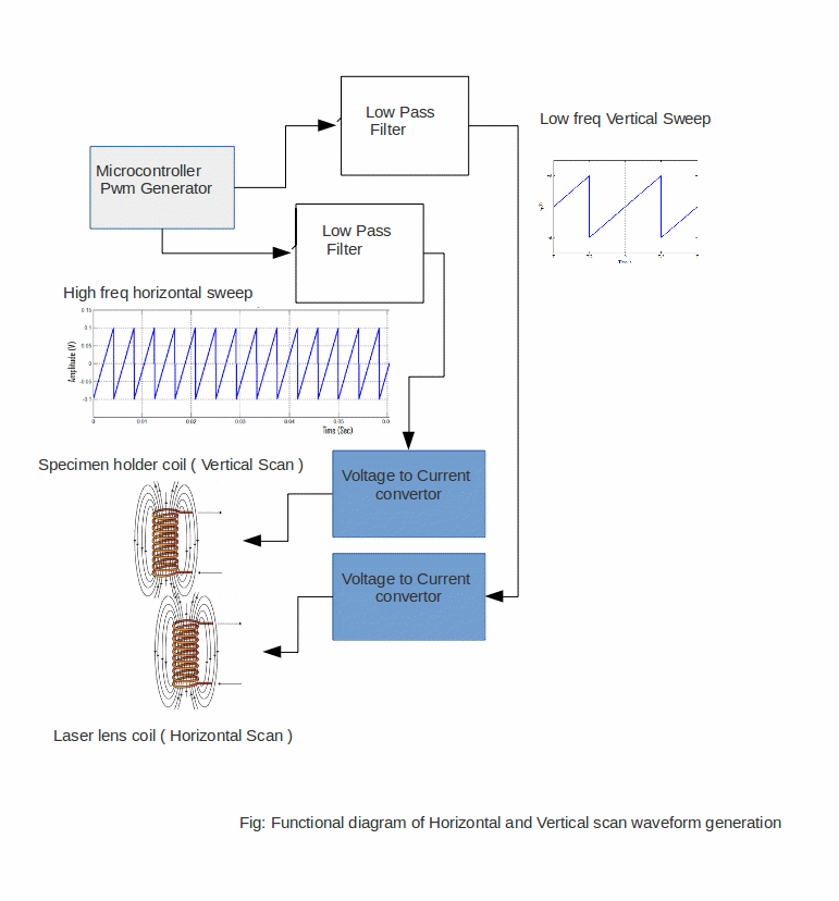
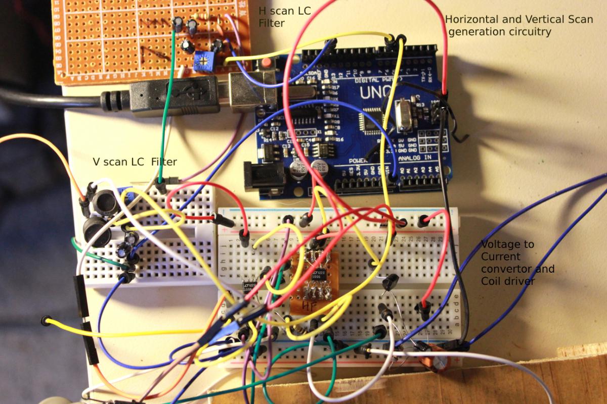
Fig: The electronics for the Horizontal & Vertical scan generation
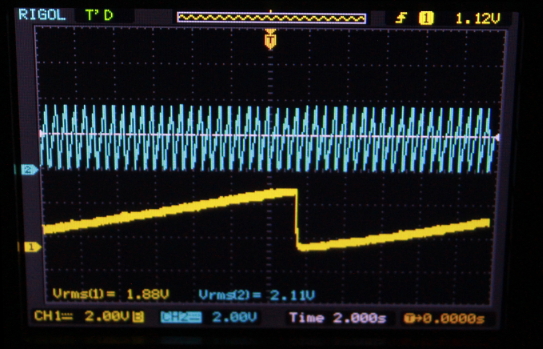
Fig: Vertical scan waveform (yellow) , Horizontal scan (blue)
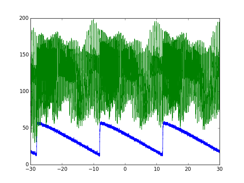
Fig: The above pic shows the 3 lines of horizontal Laser scan reflection, ie image data from specimen( green ) and the blue is the Horizontal drive signal
This is an absolutely fun project to do, its covers physics, mechanics and electronics and it taught me a lot of new things in the course of getting it going.
I found the project has no finish line, its one which you can continously improve upon.
if you have any questions drop me a line at sachins@hobbyist.co.nz