ESP8266 Door Lock
Load the final project code into Arduino IDE. Near the top of the sketch you should see the following lines:
char ssid[] = "DoorLock"; // your network SSID (name)
char pass[] = "passw0rd"; // your network password
char pin_code[] = "1234"; // The required PIN to activate the relay
Change the ssid variable to the name of your WiFi network, the pass variable to be the password for that network, and pin_code should be change to the PIN code you want to use for controlling the lock solenoid. The Arduino code will only allow the digits 0-9 and not alphabetical characters.
Then upload the code and open the Serial Monitor as before. You should see something like this:
[WiFiEsp] Initializing ESP module
[WiFiEsp] Initilization successful - 2.1.0
Attempting to connect to WPA SSID: DoorLock
[WiFiEsp] Connected to DoorLock
IP Address: 192.168.1.4
[WiFiEsp] Server started on port 80
Server started
Web browse to the IP address that you see in the Serial Monitor output and you should see the following:
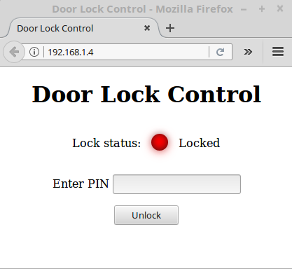
Enter the correct PIN code in the text field and click on Unlock. After the PIN is verified the lock solenoid should engage retracting the lock pin and the web page will update indicating the new state of the lock. Entering the PIN code again and clicking Lock will set the solenoid into the lock position and as before, the web page will update to show the state of the lock.
Going Further: Standalone IOT door lock (No WiFi network needed)
In its present configuration the Arduino door lock joins an existing WiFi network. If you want it to create a WiFi network of its own like with the test programs we ran earlier, this can be done fairly easily.
First, change the ssid and pass variable near the top of the code. This creates our WiFi network name and password needed to join it.
Next, comment out the the while loop in the setup() function and uncomment several lines of code beneath so you end up with something like this:
...
// attempt to connect to WiFi network
// Comment this block out if you are wanting to create an WiFi access point
// while (status != WL_CONNECTED) {
// Serial.print(F("Attempting to connect to WPA SSID: "));
// Serial.println(ssid);
// // Connect to WPA/WPA2 network
// status = WiFi.begin(ssid, pass);
// }
// Uncomment the lines below to create a WiFi access point
 Serial.print("Attempting to start AP ");
 Serial.println(ssid);
// Set our IP address
IPAddress localIp(192, 168, 1, 1);
WiFi.configAP(localIp);
// Start access point
status = WiFi.beginAP(ssid,channel,pass,ENC_TYPE_WPA2_PSK);
...After uploading you should see in the Serial Monitor evidence of a WiFi access point being created like we had earlier.
Whether this IoT project is connected to a private WiFi network or produces a network of it's own there's a great deal of fun to be had!