The Lock control is handled by a motor controller. This builds on what we have built so far, the button press now opens the lock. Then does the count down and closes the lock.
Arduino sends instructions to the motor controller via the Arduinos Digital pins 4 and 6 to the Motor controllers pins In3 and In4.
|
D4 D6 to left to pins of In3 In4 |
Action |
|
10 (HIGH,LOW) |
Motor turns clockwise |
|
01 (LOW,HIGH) |
Motor turns anticlockwise |
|
11 (HIGH,HIGH) |
Motor breaks |
|
00 (LOW,LOW) |
Motor is free |
- Arduino connects its 5v to motor controller +5V and the Ground to Ground.
- The Lock Connector contains the power to drive the lock, it’s Ground line also connects to the Motor Controllers Ground. The Locks Power line connects to the Motor Controllers +Vcc.
- The next two pins are the Locks motor and these connect to the Motor Controller pins Out0 and Out 1.
There is also two more pins on the Lock connection.
A Mont pin, that is 0v when the locks latch is closed and +v when the locks latch is open. I currently don’t test this.
The last pin is to a Setter switch, it’s like a reset button this is on the lock and does something with original controller but I don’t use it. It reports 0v when no pushed and +V when pressed.
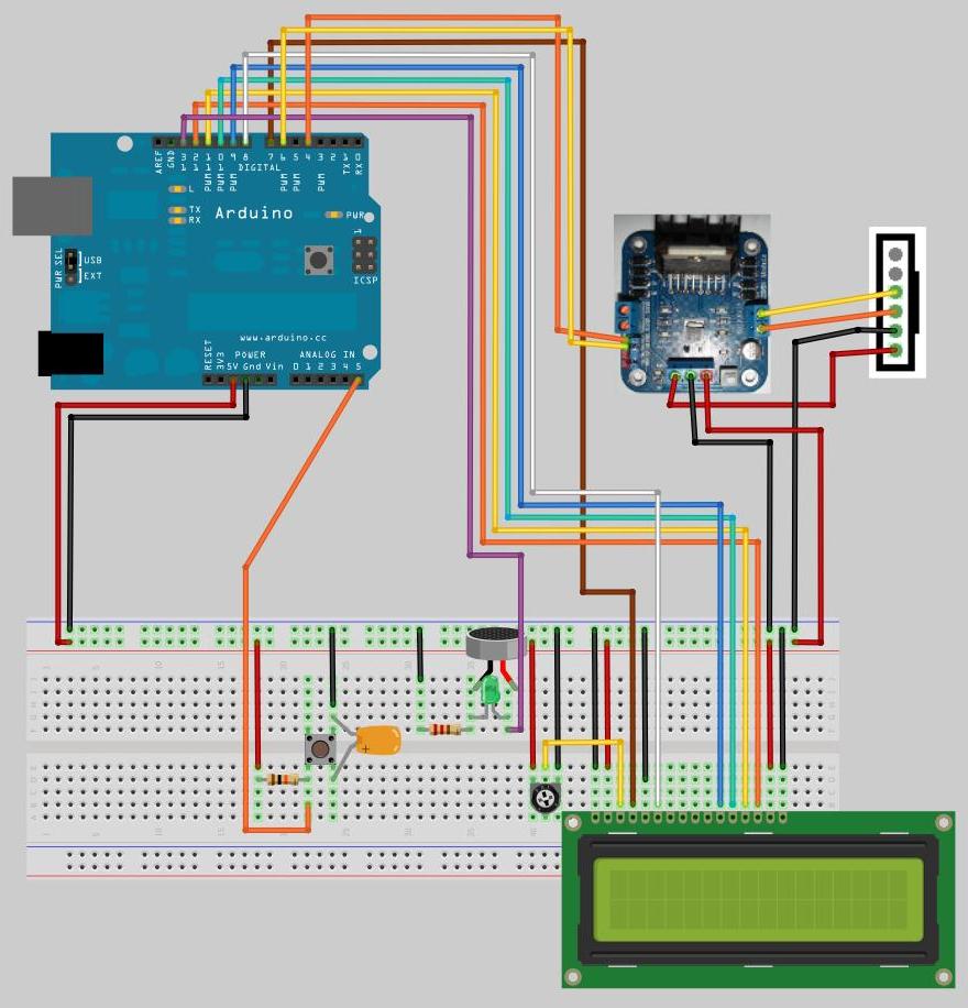
Click to see larger Image
Above you can see the wiring needed to connect the lock motor. The actual circuit may look something like this.

There are two bits of code added to control the lock when the button is pressed.
Below opens the lock.
digitalWrite(motor0,LOW); // Open lock
digitalWrite(motor1,HIGH);
delay(500); // Time for lock to open fully
digitalWrite(motor0,LOW); // Stop motor
digitalWrite(motor1,LOW);
Below closes the lock.
digitalWrite(motor0,HIGH); // Close Lock motor
digitalWrite(motor1,LOW);
delay(500);
digitalWrite(motor0,LOW); // Stop lock motor
digitalWrite(motor1,LOW);
| #include <LiquidCrystal.h> #define motor0 4 // digital pins the lock uses #define motor1 6 // initialize the library with the numbers of the interface pins LiquidCrystal lcd(7, 8, 9, 10, 11, 12); byte ch0[8] = {B11111,B11111,B11111,B11111,B11111,B11111,B11111,0}; byte ch1[8] = {B11110,B11110,B11110,B11110,B11110,B11110,B11110,0}; byte ch2[8] = {B11100,B11100,B11100,B11100,B11100,B11100,B11100,0}; byte ch3[8] = {B11000,B11000,B11000,B11000,B11000,B11000,B11000,0}; byte ch4[8] = {B10000,B10000,B10000,B10000,B10000,B10000,B10000,0}; byte ch5[8] = {B00000,B00000,B00000,B00000,B00000,B00000,B00000,0}; int beeper = 0; // Beeper flag 0 = off void setup() { pinMode(13, OUTPUT); // door beeper pinMode(A5, INPUT); // Button input - we are using as a digital pin pinMode(motor0,OUTPUT); // set lock motor pins to output pinMode(motor1,OUTPUT); lcd.begin(16, 2); // set up the LCD's number of columns and rows: lcd.print("Lock test"); // Print startup message to the LCD. Serial.begin(19200); // For Serial debugging, 19200 baud because Serial.println("Ready"); // that’s the speed the RFID card works at. lcd.createChar(0, ch0); // initialise our custom characters lcd.createChar(1, ch1); lcd.createChar(2, ch2); lcd.createChar(3, ch3); lcd.createChar(4, ch4); lcd.createChar(5, ch5); } // end setup void loop() { boolean buttonState = digitalRead(A5); // get button state buttonState =! buttonState; // Invert button state to match logic if (buttonState == true){ Serial.println(buttonState); digitalWrite(motor0,LOW); // Open lock digitalWrite(motor1,HIGH); delay(500); // time for lock to open fully digitalWrite(motor0,LOW); // Stop motor digitalWrite(motor1,LOW); lcd.setCursor(0, 1); for (int i=0; i <= 15; i++) // print 16 block characters { lcd.print((char) 0); } delay(100); for (int i=15; i >= 0; i--) { // loop through the 16 characters for (int c=0; c <= 5; c++) { // loop through the 16 characters places of the LCD screen beeper=!beeper; digitalWrite(13, beeper); // Turn beeper on or off lcd.setCursor(i, 1); lcd.print((char) c); // print our custom character delay(100); // the delays add up to about 8 seconds, // that's how long the door lock will be open for. } } // end count down loop digitalWrite(13, 0); // set beeper off digitalWrite(motor0,HIGH); // Close Lock motor digitalWrite(motor1,LOW); delay(500); digitalWrite(motor0,LOW); // Stop lock motor digitalWrite(motor1,LOW); } // end if button loop } // end main loop |