This is a basic alarm clock, it uses a serial terminal to send commands to the arduino, to set the time and set alarm times.
The Hardware components
The Program basically flows like this.
-
on startup import time table from eeprom.
-
main loop
-
check serial port for a command
-
process command
-
check time is like the alarm
-
run the alarm beeper
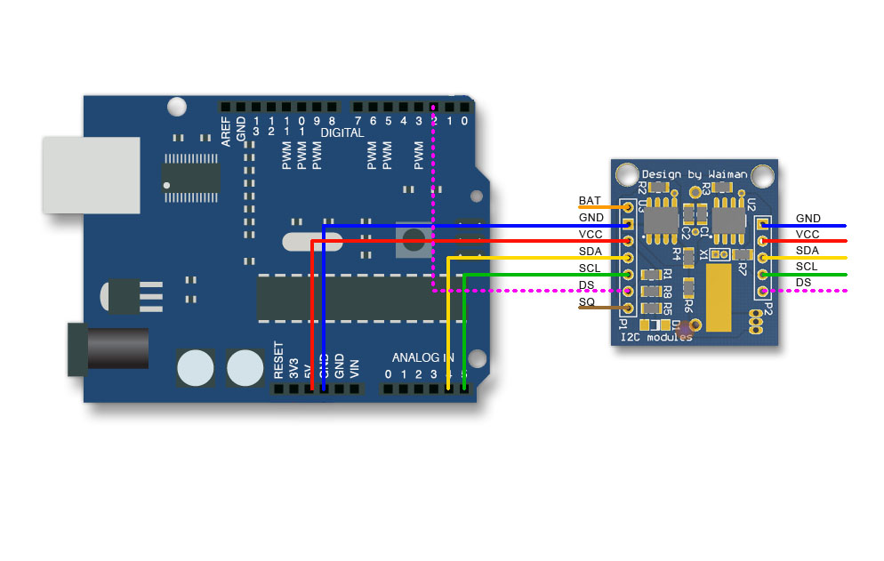
Connecting Arduino via i2c to RTC
The pins we connect from the Real time clock module to the Arduino :
|
Real Time Clock |
Arduino |
Wire colour |
|
5V |
5v Pin |
Red |
|
GND |
GND Pin |
Black |
|
SCL the i2c clock pin |
A5 |
Green |
|
SDA the i2c data pin |
A4 |
Yellow |
The clock terminal section
Commands for setting the time and adjusting , are sent to the Arduino via the serial port.
The serial port is a serial Terminal, so you could use any serial program to adjust the time table.
commands:
timeHelp - text about program usage help
timeRead - reads the clock, shows the time
void setTime(); - sets the clocks time
void showAlarm(); shows alarm times
void setAlarm(); set an alarm time
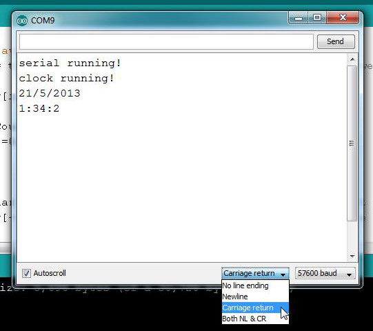
The main bit of the serial terminal is the ‘command buffer’, which is used to store the typed in commands. I don’t use Arduino string functions if you can as they hog memory. I used the standard c++ library.
The Arduino Serial monitor needs to have Carriage return on, see picture below.
That's because we read characters into the command buffer until a Carriage return is entered and then a command is processed.
|
strcspn find first occurrence of a character/number in a string strtok would do the above better. tokenizing a string
strncmp string compare strlen string length
|
I connect to the RTC with this library https://github.com/adafruit/RTClib ,
how to install a library is here http://arduino.cc/en/Guide/Libraries
setting the clock
the adjust time can be used to set the date and time of the rtc.
i just need the time settings as the dates not so important.
so i need to have a string that contains the date and a string that contains the time
|
RTC.adjust(DateTime("Jan 09 1968", "00:30:00")); // sets clock
RTC.adjust(DateTime(__DATE__, __TIME__)); // sets clock with the system time at compiling. |
Tone Alarm generation
This is basically how the alarm tones are generated
http://arduino.cc/en/reference/tone
adafruit-arduino-lesson-10-making-sounds/playing-a-scale
|
int speakerPin = 9; int tones[] = {261, 294, 277, 294, 311, 294, 330, 294, 349, 294, 370, 294, 392, 294, 415, 294, 440}; void beeep() { for (int i = 0; i < (sizeof(tones)>>1); i++) { tone(speakerPin, tones[i]); delay(300); } noTone(speakerPin); } |
Store 'time table' in arduinos eprom.
http://arduino.cc/en/Reference/EEPROMRead
http://arduino.cc/en/Reference/EEPROMWrite
The eeprom space by default filled with 255 ($FF) unless used by other programs.
We will write the first byte of the eeprom space with 42 a code meaning we have stored alarm times.
The next byte will contain the number of alarms that have been set.
That could be between 0 and 8 as that's how much space we have set aside in theAlarms array.
The following 2 bytes will be the time of the alarm in 24 hour format, first byte is the Hour and 2nd byte is the Minute.
These will be daily alarms, so we don't need to store Date, Month or Year.
On startup, the program will check to see if 42 is present and if so it will load the alarm times into an array of alarm times.
If 42 is not found then 42 will be written to the first byte of the eeprom space followed by a zero in the 2nd byte to show there are no alarms set.
Adding the alarm will be a two step process with the hour being entered first in 24 hour format and then the minutes.
The OLED
http://www.hobbyist.co.nz/?q=arduino-to-oled-display
The hobbyist example looks ok to use as it will just be text output.
|
Top Row |
SDA |
MIT |
3v3 |
PA0 |
|
Bottom Row |
SCL |
RST |
GND |
VCC |
Wiring the OLED display to Arduino
The OLED display uses I2C bus to communicate with the Arduino.
The I2C bus can support multiple devices and each device on the I2C bus has a unique address.
#define OLED_ADDRESS 0x27
The Arduino code uses this address to communicate with the OLED display and sets its internal registers and memory to display data on the screen.
Two pins SCL (A5), SDA (A4) in Arduino Uno are used for communication.
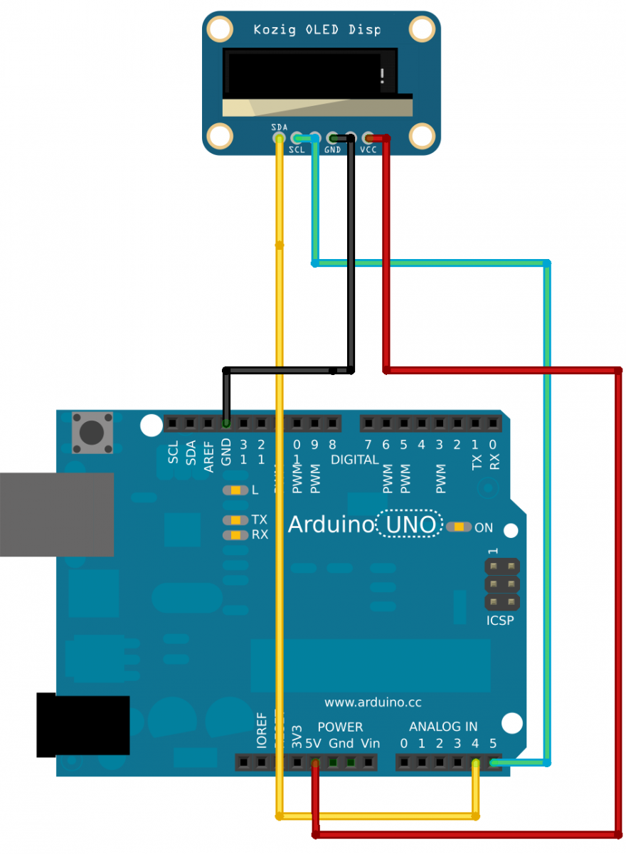
Fig 1: Wiring Arduino to OLED display#include <ZtLib.h> #include <Wire.h> #define OLED_ADDRESS 0x27
void setup() { uint8_t versbuff[16]; uint8_t temp; Serial.begin(9600); ZT.I2cInit(); ZT.ScI2cMxReset(OLED_ADDRESS); delay(5);// Reset and re-initialize, clean the cache, you need to wait a little ZT.ScI2cMxDisplay8x16Str(OLED_ADDRESS,0,0,"Hobbyist Ltd"); temp = ZT.ScI2cMxReadVersion(OLED_ADDRESS,versbuff); ZT.ScI2cMxDisplay8x16Str(OLED_ADDRESS,3,0,"OLED disp:"); ZT.ScI2cMxDisplay8x16Str(OLED_ADDRESS,5,0,(char *)versbuff); Serial.print("Version:\n"); for (int i=0; i<temp; i++) { Serial.print((char)versbuff[i]); } Serial.print('\n');
} void loop() { }
|
DHT11
This is like the DHT22, below is the basic reading DHT11 data and then writing it to the OLED.
http://www.hobbyist.co.nz/?q=bump-sensor-dht22-oled-and-arduino
|
ZT.I2cInit(); ZT.ScI2cMxReset(OLED_ADDRESS); delay(5); //Read the temp and humidity sensor once before starting server char stringBuff[16]; float h = dht.readHumidity(); float t = dht.readTemperature(); dtostrf(t, 5, 2, stringBuff); ZT.ScI2cMxDisplay8x16Str(OLED_ADDRESS,4,0,"Temp:"); ZT.ScI2cMxDisplay8x16Str(OLED_ADDRESS,4,55, stringBuff); dtostrf(h, 5, 2, stringBuff); ZT.ScI2cMxDisplay8x16Str(OLED_ADDRESS,2,0,"Humid:"); ZT.ScI2cMxDisplay8x16Str(OLED_ADDRESS,2,55, stringBuff); |
