Introduction
The GPS kit shows varied uses of the Arduino – from displaying information on an LCD screen, to saving data to an SD card, as well as reading serial data from a GPS module.
Basically, the GPS module outputs location data directly to the Arduino (software) serial in. This is stored on an SD card, and a single switch and LCD screen help provide an interface to the operation.
Once data has been collected, it can be uploaded to a computer. From there, it is displayed on a Google map.
Who is it for?
General experimenters and tinkerers with a small amount of ability in electronics and software or ability to read and learn.
The kit uses the Arduino hardware/software platform but mostly it is ‘plug and play’.
It requires a small amount of soldering to solder the header pins onto the LCD module and a little work to attach a 4 core cable to the small pads on the GPS module.
###[add image - whole unit]###
Required knowledge (or 'google it') / tools
* Small amount of electronics knowledge (which way round an LED goes, basic breadboard wiring etc)
* Installed copy of Arduino 1.0 1.01 or 1.02 etc (from http://arduino.cc/en/Main/Software), and understanding of the comm port the Arduino hardware is attached to.
* Ability to install sketches and libraries into the Arduino Software
* Ability to upload sketches to Arduino board
* Ability to read code to troubleshooting level
Procedure:
Rather than building the whole kit and testing it at once, we will part-build and test in stages.
Stage 1:
GPS module wiring and test
If you have a ####[ftdi? cable - do the modules come with this?? ]#### you can connect the GPS module directly to your computer with the usb connector.
You'll need a terminal program and/or a GPS program for your operating system plus drivers to connect (software-wise) the USB data to the program.
####[not sure how to finish this off - recommended program and drivers for windows/linux? WIN - RealTerm; GPS Diag / u-center; PL 2303 USB-serial driver]####
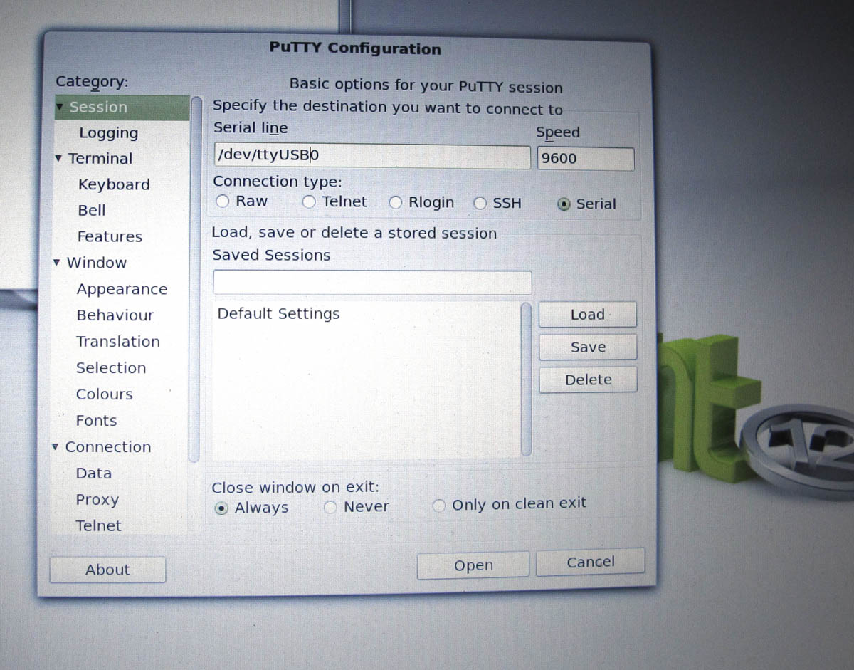
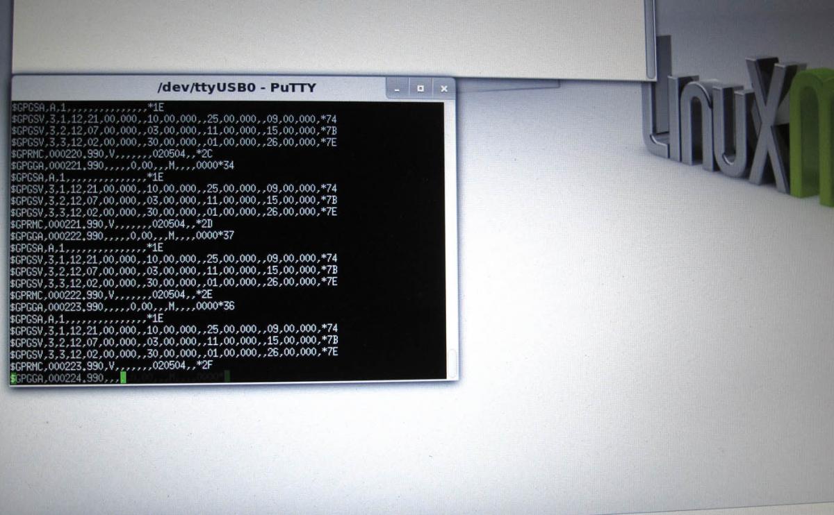
With a terminal program you should be able to see raw GPS data directly from the sensor. If you can find a GPS program, this will present the data a little nicer.
In the pictures you can see the config for PuTTY terminal program on Linux, and the raw data output.
Stage 2:
Rewiring the GPS module to connect to Arduino
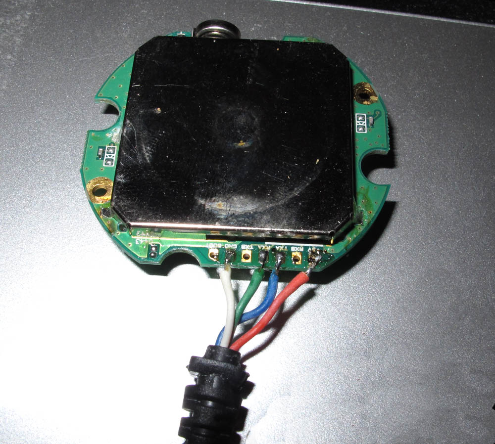
1) Open the GPS module, desolder the existing cableif necessary and attach the 4 core cable to GND, 3.3V, TXA and RXA pads. Note which colour wires you attach to which pins.
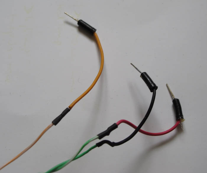
2) Cut two of the shorter breadboard connecting wires (with pins on the ends) in half. On the other end of this cable, strip and attach a connect wire to each wire of the cable. This allows you to plug each wire into the Arduino headers easily. Use electrical tape or similar to insulate the connections.
In the picture below, breadboard connect wires have been cut in half and soldered to the ends of the wires from the GPS,
so that they can easily be plugged into Arduino pins.
Once you've done this there is a 3rd way to test by connecting the GPS to the Arduino.
Attach each wire to the appropriate header pins on the Arduino:
a) GND from GPS to GND on Arduino
b) 3.3v from GPS to 3.3v on Arduino
c) TXA from GPS to RX (pin 0) on Arduino
d) RXA from GPS to TX (pin 1) on Arduino
Stage 3:
Create an Arduino sketch:
//Start
//Sample Arduino 1.0 sketch to test GPS module data input
// Run this sketch and open the serial monitor.
// A data stream from the GPS should be seen, updating each second.
byte gpsData;
void setup()
{
Serial.begin(57600);
}
void loop()
{
if (Serial.available()>0) // if there is data coming into the serial line
{
gpsData = Serial.read(); // get data
Serial.write(gpsData); // send it to the serial monitor
}
}
//End
This sketch just reads straight from Arduino Rx pin and outputs it again. The serial monitor can see this, so once this sketch is uploaded to the Arduino, open the serial monitor – make sure it is set to communicate at 57600 baud, otherwise you'll get junk.
If all is well, you should see lines of data being updated each second.
GPS Data
$GPGSA,A,3,04,05,,09,12,,,24,,,,,2.5,1.3,2.1*39
$GPGSV,2,1,08,01,40,083,46,02,17,308,41,12,07,344,39,14,22,228,45*75
$GPRMC,123519,A,4807.038,N,01131.000,E,022.4,084.4,230394,003.1,W*6A
What is this stuff? Well, it’s the core data for this kit – NMEA sentences which describe how many and which satellites have been found, and importantly for us, location data.
Note that these GPS modules may initially take a while to find and fix on satellites – anywhere from 1 – 5 minutes. As long as you see something coming out each second, the module is probably working.
Note that in line 3, after the 2nd comma here you see the character A - for Active - this means the module has got a fix on some satellites. If it is a V (for Void) then a fix can't be acheived - the module often needs to be outside to get a good signal. This line also has the other data we want:
     4807.038,N   Latitude 48 deg 07.038' N
     01131.000,E  Longitude 11 deg 31.000' E
     022.4        Speed over the ground in knots
     084.4        Track angle in degrees True
     230394       Date - 23rd of March 1994
If line 3 ($GPRMC) is showing V, then you probably won't see any coordinate or speed data.
You can find much more out about the meaning of the NMEA data by going to:
http://www.gpsinformation.org/dale/nmea.htm
If you see this data, this shows that the wiring to the GPS module is correct and all your Arduino setup is fine. Note that we will be using different Arduino pins in the final setup.
Stage 4:
SD Card shield test
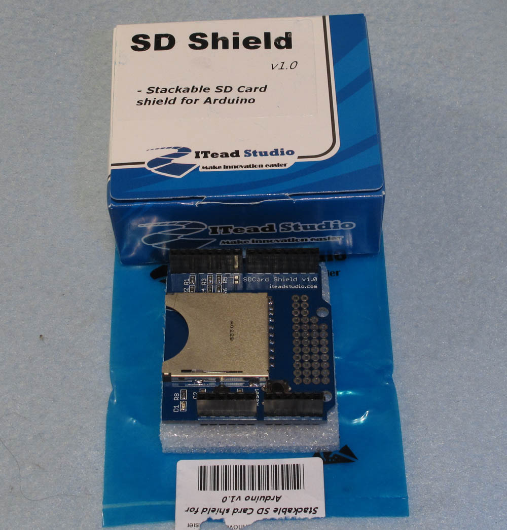
1) Attach the SD card shield to the Arduino. Its pins just slot into the corresponding headers on the Arduino board.
2) Make sure all pins have seated in the correct place.
3) Make sure power is not connected to the Arduino. Plug in an SD or micro SD card. Note that this may not work with an SDHC card and also that it should be formatted as either FAT16 or FAT32
4) In the Arduino software programme there is an example sketch under “SD” called ReadWrite, which just writes data to a file on the card (creatng the file if it doesn't exist). Change the CS pin to 10 (or SD.begin(10) ) Upload this and run it.
5) Open the serial monitor and you should see that data has been written to and read from the card.
5) If you don't believe that this has done anything to the card you can disconnect power, pull out the SD card and plug it into a card reader. You should find a file called test.txt with "testing 1, 2, 3" in it.
If the data looks correct then the Arduino / SD card shield are connected and working.
Stage 4:
LCD module soldering and test
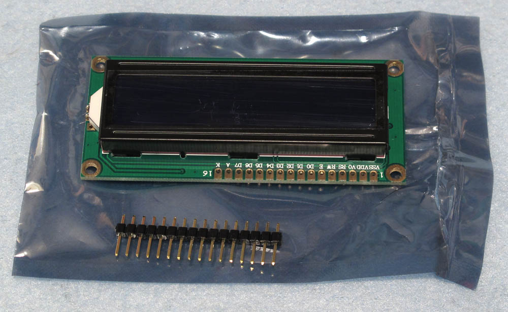
1) Take the header pins and place the long ends in a breadboard (just to hold them steady - you could also use a vice or a piece of thick cardboard; anything to hold it all steady while soldering, but avoid using polystyrene because there's a chance that static could damage the module.
2) Place the LCD module circuit board holes over the top of the pins so that they poke through the holes – make sure they are aligned so that all 16 pin ends go into the 16 holes.
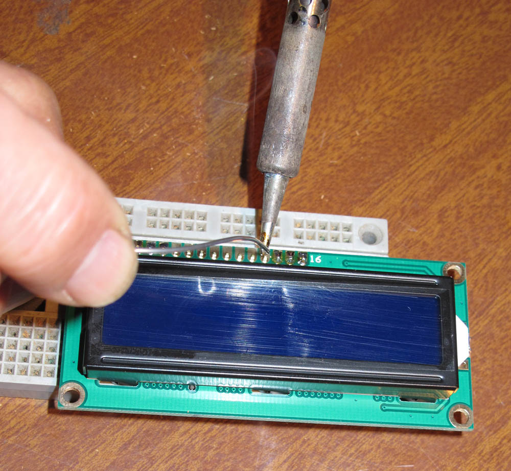
3) Solder the pin ends to the board. (You can solder just a couple to anchor them, then unplug from the breadboard – so you don’t heat the breadboard up too much).
4) Now the LCD module header pins can be plugged back into the breadboard.
5) Remove the SD Card shield from previous test.
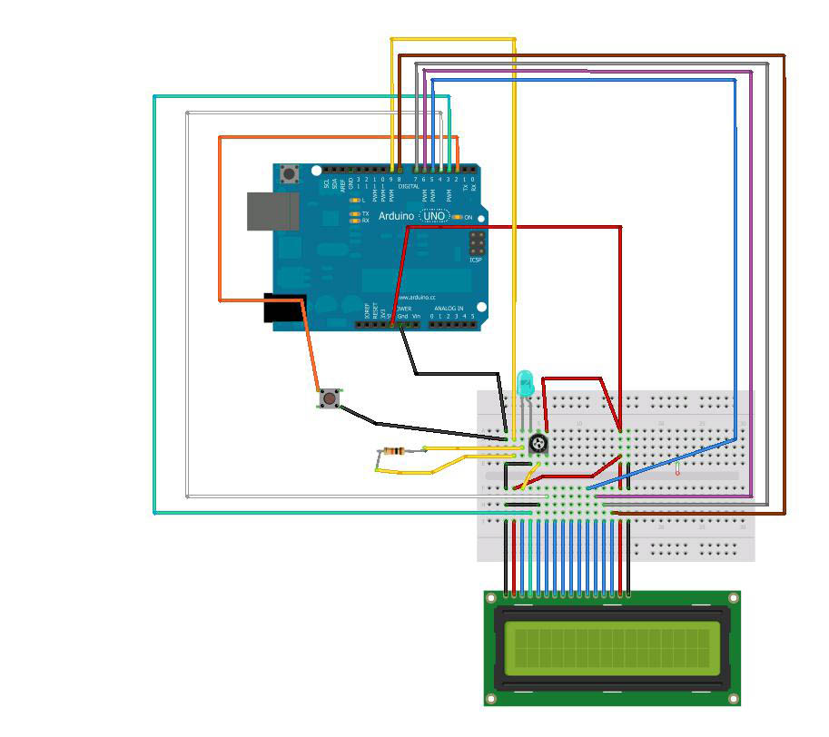
6) Follow the wiring diagram carefully, so that the data lines, power and backlight lines are attached to the correct places on the Arduino.
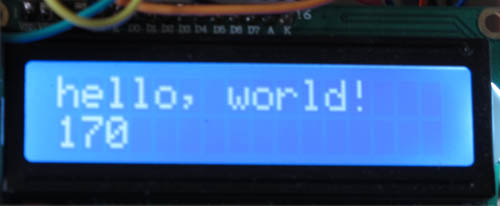
7) In the Arduino software programme there is an example sketch under “LCD” called ‘Hello World’, which just writes "Hello World" to the LCD screen. Upload this and run it.
NOTE - if you are wiring as above, the pins that the LCD connects to the Arduino are different and the sketch should be modified. Find the line that says :
LiduidCrystal lcd(0, 1, 2, 3, 4, 5);
Change it to:
LiduidCrystal lcd(3, 4, 5, 6, 7, 8);
8) You will need to adjust the potentiometer to get contrast on the LCD. You may first see all the LCD sections light up, then see the text displaying.
If you see the text, you know your LCD module is working and is wired up correctly and talking with the Arduino.
Now we are ready to build the real thing