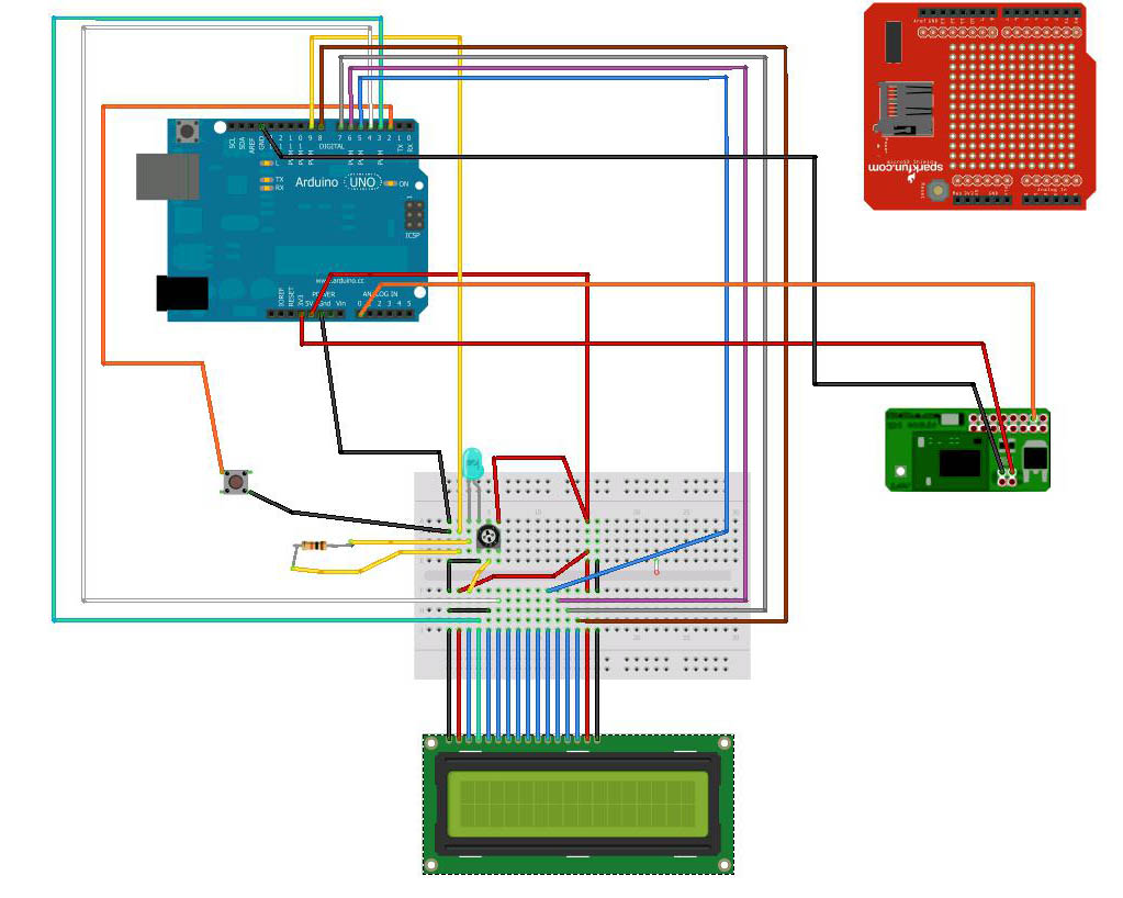
Putting it all together
This section describes the process of putting together the complete system - GPS, SD, LCD with Arduino, now that you know everything individually works and you are familiar with how each part does its' job.
Its a bit different this time because we need to use different pins in some places due to the fact that we need the Arduino pin 2 for an interrupt on a switch.
You will need to download and install the test and final Arduino sketches and also install tinyGPS library.
Create a folder called GPS in your Arduino sketches folder for all the sketches related to this project. Unzip the following files into that folder. Once you restart the Arduino software you should see the GPS folder and the sketches inside that.
Hardware test sketches:hardware_testing
Final sketch: GPS_SD_upload_project
Note - the fourth page has more troubleshooting tips.
Operation
On power up the LCD will display an initial message and the LED will blink a few times.
The unit will be in mode 1 and waiting for the GPS to connect to satellites and get a fix.
Once a fix is obtained the LED will flash approx once per second, and other modes can be cycled though (until a fix is obtained, recodring and uploading cannot be selected)
At this point, if the switch is momentarily pressed, the unit will go to mode 2 and will log GPS data to the SD card.
Data logging will continue until the switch is pressed again, at which point the unit goes to mode 3 - logging finished.
One more switch press will result in mode 4 - SD card data uploading where the card data is pushed out on the serial port.
The unit goes back to mode 1 after the data upload.
In order to pause and restart logging you will have to go mode 3, to mode 4, wait for upload, then press the switch for mode 2 - logging mode.
Stage 1:
LCD and SD Card shield
1) Remove all the wiring to the Arduino that you did previously, so we can start with a clean slate.
2) Attach the SD card shield.
3) Wire the LCD/breadboard wires to the header pins on the SD Card shield that correspond with the ones directly on the Arduino. Leave out the GPS, LED and switch for now.
4) Download the sketches file.
5) Add a folder to your Arduino sketches area (usually My_documents/Arduino) called GPS
6) Install all the sketch files in here. When you next start up Arduino SDK you should see the folder and sketches in the Sketchbook area.
7) Load the SDReadWrite_lcd_test sketch.
This attempts to write/create a file called t3.txt, then write an ascending series of integers into it, and it displays this on the LCD. (If you use a small SD card it might eventually fill it up.)
If you see the LCD displaying a counting sequence then all your wiring is good.
Stage 2:
Adding in the GPS and library
1) Attach the four wires from the GPS to the SD card shield header. Make sure you use the 3.3v voltage, not 5v. In this case, RXA and TXA on the GPS module go to Arduino pins A0 and A1 (because the SD card shield uses the serial TX and RX pins).
2) Download the most recent tinyGPS library from http://arduiniana.org/libraries/tinygps/ (scroll to near the bottom of the page) and install in the Arduino Libraries area.
3) Load up the Arduino sketch - gps_lcd_test, which will prove that your GPS module is still working and is wired in correctly.
If you see "valid fix" LCD, congratulations - all is good and the GPS has found satellites and got a fix! If you see "no fix" then the GPS module is either not working or can't find a satellite. Make sure the module is outside or can "see" the sky and make sure it is all connected properly. You can open the serial monitor and see more detail of the communication between Arduino and GPS module.
Stage 3:
Switch and LED
A switch is connected to digital pin 2 on the Arduino. When pressed it triggers an interrupt in the sketch and this changes modes. An LED is added which lights when a GPS fix is found.
1) Wire up the switch and attach to digital pin 2
2) Wire up the LED and resistor. Connect to digital pin 9
3) Test with the following sketch - switch_led_test
You should see the LED initially flash on and off a few times then slowly flash once each 2 seconds. When you press the switch once, the LED should flash twice per 2 seconds, again and it should flash 3 times, again and it should flash 4 times. If you press it once more it will return to flashing once each two seconds.
Stage 4:
Final sketch
The electronics should all be ready. Now we just need the final sketch.
This uses two new libraries SoftSerial – which gets the serial data on any Arduino pins, and tinyGPS, which takes a serial string, checks and pulls out GPS information into an object which you can then query for specific parts of the data.
1) Upload sketch - GPS_SD_upload_project and open the Serial monitor
2) Wait for GPS to get a fix
3) Change to mode 2 - Logging data - if you dont move around with the unit you'll get a set of identical points, but for this test, that is okay.
4) After 10 sec or so (10 points) change to mode 3 - Uploading. You should see a data stream of your GPS points that have been saved to the sd card
5) You can also power down and put the SD card into a computer with an SD reader and find the datalog.txt file, to view the data directly on the card.
See page 4 for troubleshooting tips.