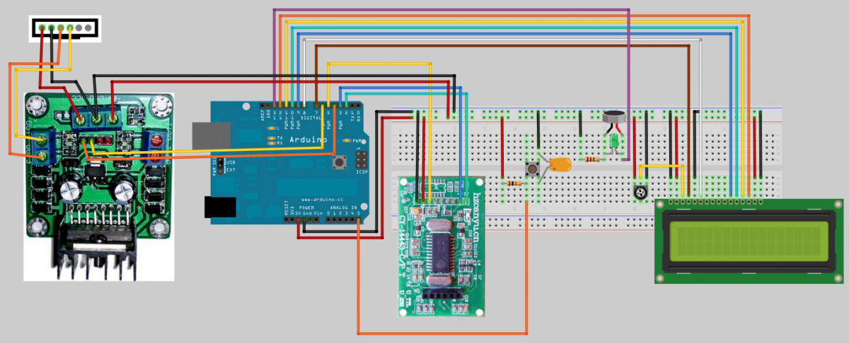
Here, we add the RFID module to what we have put together to date.
The RFID module communicates with its UART serial serial port to the Arduino via the SoftwareSerial library. Also on the RFID module is a signal pin. When a RFID Tag is within range (6cm max) an LED on lights up and the signal pin changes its state. That change of state can be monitored by the arduino and so triggers other actions, like reading the Tag ID.
Commands are sent of through the software serial port to the RFID module.
The RFID module supports from 3.3v and 5v and it works at 13.56Mhz.
The integrated reader has a detection distance of up to 6cm at 5v.
The command and response data structure always start with the hex bytes 0xAA 0xBB. The next byte contains the length of the command or data, followed by the bytes of the command or data. The last byte is a CRC checksum of the bytes that make up the length and command or data.
RFID Data Format:
| Head | Length | Command | XOR Checksum |
| AA BB | 01 | 01 | 03 |
With the RFID Serial port baud rate is set to 19200 a request read Tag command is sent.
Its format in HEX is AA BB 02 20 22 (5 bytes).
If for some reason there is no Tags within the working area of RFID module, then the RFID module responds with an error code AA BB 02 DF DD (5 bytes). The error code is the inverse of the command requested.
The read command is Hex 20 and its inverse is DF, you can see this easier where you look at the binary 00100000 inverse is 11011111.
If there is a Tag in range then the RFID module reponds with the Tags ID
ie: AA BB 06 20 5E 97 25 C7 0D (9 bytes). 5E 97 25 C7 is the Tag ID.
Below are two programs for the Arduino, the first is used to find out what the Tag ID values are and the second uses those Tag ID values to activate the door lock.
Click to see larger Image
The 5 wiring for the RFID module:
| RFID Module | Arduino |
| Ground (Black) | Ground |
| +5v (Red) | +5v |
| Signal (Yellow) | Digital Pin 5 |
| Serial Tx (Blue) | Digital Pin 3 |
| Serial Rx (Green) | Digital Pin 2 |
|
#include <SoftwareSerial.h> // define array for the response. byte response[32];
void loop() // if this byte is the invert of the command sent then it's a error // (1s complement of the command) - 20 if read or DF if error // the data returned, [byte 4] -> [byte 4]+([byte 2] - 1) if (response[3]==0x20) // was read ok? // if so. loop through the ID number displaying it to the LCD { // send command to read RFID card |
Below is the code use to read and RFID Tag and if it's the right one, will open the lock.
Note the line, byte theKey[] = {0x6C,0xD0,0x1E,0x54,0xD0};
The numbers in red is the RFID Tag ID key that we got from the previous program,
you will need to change this to match your RFID Tags ID number.
Complete code for available on purchase
Ending notes:
Above is a basic look at working with RFID module but is can do so much more and so here is a collection of notes that I collected when developing this project. Have a look at this PDF if you would like to know more about working with the RDIF reader/writer.
Pin Definitions of RFID card module:
| Pin | Symbol | IO Type | Description | Arduino or notes |
|
J1-1 |
RXD |
I/O |
Uart Receiver | serial link to arduino pin 2 |
|
J1-2 |
TXD |
I/O |
Uart Transmitter | serial link to arduino pin 3 |
|
J1-3 |
OUT1 |
I/O |
Output 1 | |
|
J1-4 |
OUT2 |
I |
Output 2 | |
|
J1-5 |
RST |
I |
Reset, active-low floating for power-on reset by default |
|
|
J1-6 |
BUZ |
I |
Buzzer output, high level drive | Could be for different model |
|
J1-7 |
SIG |
O |
Interrupt output, LOW level indicates card in the field |
arduino digital pin 5 |
| J1-8 |
VCC |
Power |
Power Positive | to 5v [3v3 can be used but has a smaller field range] |
| J1-9 |
GND |
GND |
Power Negative | to gnd |