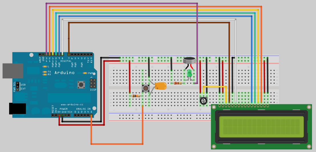
RFID Kit Step 1: wiring up the LCD
Below is the wiring diagram for connecting up a LCD screen, a buzzer and a button.
Connecting of the LCD screen is the same the LadyAda Wiring up a character LCD to an Arduino. So I will not cover the ins and outs of that and just deal with the custom characters, buzzer and the button.
We use custom characters to display a countdown bar, each character is made up of 7 rows and 5 columns. Below is a representation of the custom characters used from full to blank.
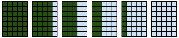
A line of 16 full custom characters are printed to the LCD, then one by one the last character on the display is replaced with the next custom character until it becomes blank and it moves onto reducing the next screen character position.
As each segment is removed Pin 13 is changed from HIGH to LOW or LOW to HIGH causing the speaker to beep.
On the wiring diagram you can see I used a 200Ω resistor connected to the speaker so it’s not too alarming.
To start the LCD count down you just put the button. This button is wired up with a hardware debounce,
which consists of a 10kΩ resistor and a 100nF ceramic capacitor.
Hint: if the count down starts right away without the button pressed, double check the wiring of the button for all connections.
Click to see larger Image

|
// LCD count down with button and beeper. #include <LiquidCrystal.h> // initialize the library with the numbers of the interface pins byte ch0[8]={B11111,B11111,B11111,B11111,B11111,B11111,B11111,0}; void setup() lcd.begin(16, 2); // Set up the LCD's number of columns and rows: Serial.begin(19200); // Serial debugging 19200 baud, the speed the RFID card communicates at. Serial.println("Serial Ready");
{ // loop through the 16 characters in row { // loop through the 5 places that make up a character |