The IR thermal viewer kit allows you create a heat map of an area of interest to determine where heat loss occurs. A popular application for this is to see where heat is escaping from around windows and also the hot water cylinder.
Kit contents:
- Arduino Nano
- Breadboard
- Breadboard power supply
- Two servo motors
- Gimbal
- Infra Red thermal sensor
Additional items:
- DC power supply for the breadboard power supply
- Small block of wood or similar for the gimbal
Assembly
We'll begin with assembling the servo motors into the gimbal and mounting the IR sensor to it.
Attach the cross-shaped adapter into the base by installing two screws from underneath. When you have completed constructing the gimbal you may like to consider screwing the base to a solid object such as small piece of wood. This will provide stability when the servos are operating and will prevent it from tipping over.

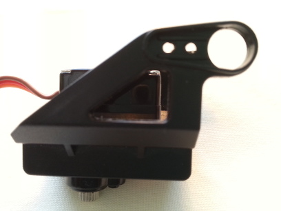
The frame for the bottom servo has two halves and come together on the left and right side of the servo. Ensure the servo gear is pointing downwards and the wires protrude to the rear of the frame as this will attach to the base. Install two screws on the left hand side to hold it together.

Next, assemble the top section of the gimbal. The servo is held in with two long screws, two circular spaces and two nuts. Attach this section on an upwards angle onto the base. Push the white rounded servo arm into place on top of the servo gear. Although you can install the screw in the servo arm you may need to adjust it later on, which would require the screw to be removed. The gimball should operate fine without the screw in place for the time being as the gear of the servo will make a firm connection.
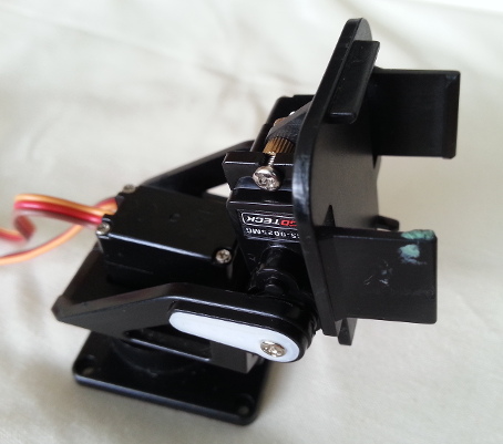
When fully assembled the gimbal will looks like this:

With the gimbal now assembled, install a screw with a washer underneath the base through the centre of the cross-shaped adapter and into the gear of the X servo. This will help keep the base and servo together firmly.
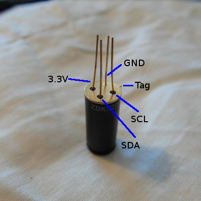
Wire everything together by starting with the IR sensor. Looking at the underside of the sensor so the ends of the pins are facing towards you, a small metal tab can be seen. With the tab pointing upwards the four pins in a clockwise direction are, SCL, SDA, Vcc and Ground. These should be connected to the Arduino Nano on pins:
A5 - (SCL)
A4 - (SDA)
3.3V - 3.3V Arduino
GND - GND Arduino

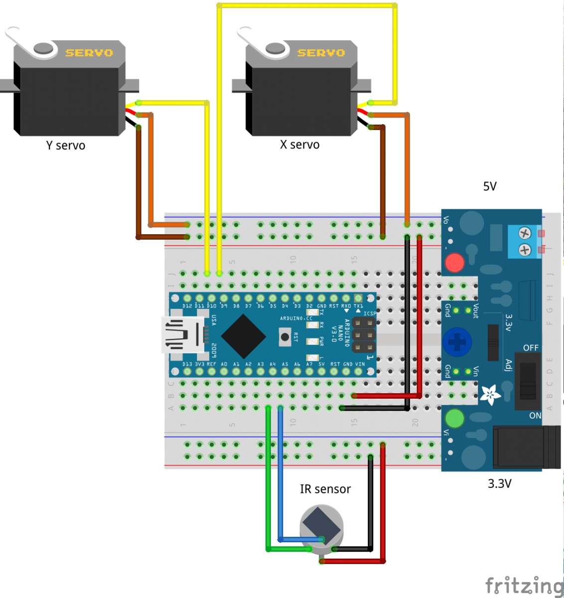
The entire circuit is shown in the following schematic:

The X servo is the servo in the base of the gimbal while the Y servo is at the top with the IR sensor mounted alongside it.
The breadboard power supply in the diagram will be slightly different to what you have been provided with but it still inserts into the breadboard in the same way.
IMPORTANT: You will need to ensure the top jumper is set to 5V so the servos get enough power while the bottom jumper needs to be set to 3.3V for the IR sensor.