Modules

Image: 

RFID Reader Module

Description: 

13.56MHz RFID module

Interfacing this module to Arduino cannot be easier, it's in TTL SPI interface. It can directly connect to SPI pins of Arduino and you are good to go.

The tutorial linked below shows the steps to get it going.

Operating voltage: 3.3 V
Sensing distance: 0 - 40 mm

Pin Definitions of RFID card module:

See this page for tutorials on how to use this RFID module.


Datasheet of the NXP processor used:

https://www.nxp.com/docs/en/data-sheet/MFRC522.pdf

Tags: rfid reader, what is rfid, about rfid, usb rfid reader, what is rfid reader, rfid a, rfid rfid, tags rfid, rfid tags


Catalog: 

Price: $39.90

Real Time Clock Module

Description: 

Arduino Tiny RTC I2C Real Time Clock

This Arduino Tiny RTC I2C module incorporates the DS1307 I2C real time clock IC and the 24C32 32K I2C EEPROM storage. What's more, it has a DS18B20 temperature sensor on board. All of this in a tiny package of 25mm x 28mm x 8.4mm. It comes with a LIR2303 rechargeable lithium battery, and a charging circuit is included in the module. When the temperature sensor is off, the RTC module can run for 1 year on a single charge.

This module is used for applications such as datalogging, timing applications ex. turning on the sprinkers at 4pm in the evenings. Since the module is self powered the time data is maintained even if the Arduino is powered off, allowing for building low power systems which can run for a long span of time without change of batteries.


Specs of DS18B20 Temperature Sensor

  • 3.0-5.5V input voltage
  • Waterproof
  • -55°C to+125°C temperature range
  • ±0.5°C accuracy from -10°C to +85°C
  • 1 Wire interface

Wiring the RTC to Arduino

arduino to RTC

The most useful pins are duplicated from P1 to P2. If needed, the pin "BAT" can be fed into an ADC pin for monitoring the battery voltage. The pin-outs are explained below. Connecting "VCC" to 5 V will trickle charge the onboard battery.

Arduino Tiny RTC I2C Real Time Clock Pinout

PIN Description Comment
BAT Battery voltage To monitor the battery voltage, or not connected
GND Ground Ground
VCC 5V supply Power the module and charge the battery
SDA I2C data I2C data for the RTC
SCL I2C clock I2C clock for the RTC
DS DS18B20 Temp. Sensor output One wire inteface
SQ Square wave output Normally not used

The I2C wires "SDA" and "SCL" are the data line and clock line, they should be connected to the corresponding pins depending on the Arduino board.

Board I2C / TWI pins
Uno, Ethernet A4 (SDA), A5 (SCL)
Mega2560 20 (SDA), 21 (SCL)
Leonardo 2 (SDA), 3 (SCL)
Due 20 (SDA), 21 (SCL), SDA1, SCL1

Example code is available here.

For more detail, please visit the Arduino Wire Library.


Schematics

The schematics of this RTC module can be downloaded here.


Catalog: 

Price: $17.99

USB Servo Controller - 24 Channels

Description: 

USB Servo controller 16 channels


Specs:

  • Mini USB 24 Channel Servo Motor Driver Controller Module
  • Specification:
  • 32-bit CPU
  • Power of servo and control board are separateChip
  • Power Supply: 4.5V ~ 5.5V ( USB powered)
  • Servo Power Supply: Generally DC 5V (base on the servo you use)
  • Channel: 24 ( servo speed adjustable)
  • Communication Input: USB or Serial Port(TTL)
  • Signal Output: PWM (accuracy 1us)
  • Servo Motor Resolution: 1us- 0.045 degrees
  • Baud Rate: 9600- 19200- 28400- 57600- 115200- 128000 (recognized automatically)
  • Dimensions: 51.0 x 43.5 x 1.6mm
  • Control Mode: USB and UART (TTL)
  • Flash Memory: 512K ROM
  • Package included:1 x 24 Channel USB Servo Motor Driver Controller Module


Description:


This is a 24-channel: mini-USB servo controller.

A mini-USB cable is included

Ideal for 6 legged robots or similar.

It uses a 32-bit processor, fast response and stable operation. USB interface, can be directly interfaced to a pc. Self-detect Baud-rate (9600, 19200, 38400, 57600, 115200, 128000)

Example
Serial.begin(115200); // Set baud-rate to be 115200
Serial.print("#1P1200T1000\r\n"­); // Turn channel 1 on at 1200 position for 1000ms.
Serial.print("#1P1200T1000#2P1600T1000\r\n"­); // Turn chanenl 1 and 2 simultaneously

This is the tutorial to show how to use this servo controller.

Catalog: 

Price: $49.00

Relay module 8 channels: For controlling power appliances

Description: 

Module consists of 8 relays. Each relay is connected to a current  buffer so that you can connect them directly to a Microcontroller.

Using these relays you can easily control power appliances, the relay is rated for 230V 10Amps.


This can be easily interfaced with Arduinos.

The Module has 9 LED's, one for power and 8 for indicating relay signals.

This module comes with a ribbon cable for easy interfacing of the relays to the Micro.


Rating:  10A 250V AC

Input voltage: 5V DC

Catalog: 

Price: $29.99

A4988 Stepper Motor Controller

Description: 

This is a single channel stepper motor controller that support a variety of micro stepping functions. It's recommended for building Reprap 3D printers and any other Stepper motor application.

Typical wiring configuration

Controller Arduino Comments
/ENABLE GND To enable
MS1 GND Select resolution
MS2 GND Select resolution
MS3 GND Select resolution
/RESET VDD no to reset
/SLEEP VDD not to sleep
STEP I/O Arduino generates pulses to STEP, each pulse gives one step turn
DIR I/O High or low to control direction
GND GND
VDD 5V 3 - 5.5v, typ. 5V
1B Steper motor phase A
1A Steper motor phase A return
2A

Steper motor phase B

2B Steper motor phase B return
GND GND

VMOT

Steper motor voltage supply 8 - 35 v, typ. 12v


For documentation and more detail, please visit

http://reprap.org/wiki/StepStick

Input voltage: 8 - 35 V

Current rating: 2 A


Datasheet download


tags: stepper motor, stepper motor controller, stepper motor driver 

Catalog: 

Price: $15.99

L298 Motor Controller

Description: 

This is a low cost motor controller. Although it's not an Arduino Shield, it can be used with Arduino or any other microcontroller platforms. This module allows you to connect 2 DC motors and have total control of them from the arduino. It also can be used to control one 4-wire stepper motor. Due to its high current rating, it's perfect for a single channel heavy duty stepper motor controller.

It allows you to move each DC motor
- Clockwise
- AntiClockwise
- Stall
- Control motor speed

A 4-way stripped wire is included.

This motor controller uses a L298 H-bridge IC
deliveries output current up to 2 A each channel. The speed control is achieved through conventional PWM which can be obtained from Arduinos PWM output Pin 5, 6, 9 and 10.

Specs:
Peak Output Current (each Channel)
- Non Repetitive (t = 100 ms): 3 A
-Repetitive (80% on -20% off; ton = 10 ms): 2.5 A
-DC Operation: 2 A
Analog voltage input:  
Vcc input:
7 - 35 V with jumper J3 short circuit, which gets regulated to 5 V and it's available on the +5 V terminal.
5 - 35 V with jumper J3 open circuit, a seperate 5 V input is needed to the +5 V terminal.
Digital voltage input: VD = 5 V (7 V max), this is output 5 V when jumper J3 is short circuit, and input 5 V when J3 is open circuit.
Max power dissipation: 20 W

There is a voltage regulator that regulates the Vcc to 5 V for digital use.

For more detail, please see


Catalog: 

Price: $18.00

Relay module 4 channels: For controlling power appliances

Description: 

Module consists of 4 relays. Each relay is connected to a current  buffer so that you can connect them directly to a Microcontroller.


Using these relays you can easily control power appliances, the relay is rated for 230V 10Amps.


This can be easily interfaced with Arduinos.

The Module has 5 LED's, one for power and 4 for indicating relay signals.

This module comes with a ribbon cable for easy interfacing of the relays to the Micro.


Rating:  10A 250V AC

Input voltage: 5V DC

Catalog: 

Price: $20.00

Bluetooth Module (Master)

Description: 

Bluetooth Module (Master):

This is the HC-06 Bluetooth module, master. It can talk to the HC-06 Bluetooth module, device.

Please note:

  • HC-06 master can only connect to HC-06 device.
  • The role of a HC-06 Bluetooth module master and a HC-06 Bluetooth device cannot be interchanged, its defifined in its firmware, which is proprietary.
  • The name of the master module cannot be changed, and other commands are the same as the device module.

Once the master detects a slave module with the same paring code, it will establish the connection. and next time, even after power down, once the master module detect the same slave module, it will automatically connect to it even other slave modules are also nearby. The master module recognizes that specific slave module through it's MAC number. A master module that is mated with a slave module has a slow flashing LED. Once connection established, its LED stays on. To reset the MAC number, press the button on the master module, or give the 'key/wake' pin a logic high impulse. Once it's reset, and if there are more multiple slave modules in the vicinity with the same paring code, the master module will randomly pick one to connect, and will again, lock into that module until the reset button is pressed.


Catalog: 

Price: $25.99

CP2102 USB to Serial converter

Description: 

USB-RS232-1_small.jpg

USB-RS232-2_small.jpg

USB-RS232_small.jpg

This is a USB to Serial (TTL level 5V) converter. It is an essential for embedded system developers who want their devices to communicate to PC via UART interface, just like the FTDI cable does.

It is powered by the USB connection to 5 V. The digital I/Os (TXD, RXD, RTS, CTS) are 3.3 V logic, and the VCC is 5 V. It is highly recommended to use this converter to configure our Bluetooth module. A 6-way stripped cable and a USB extension cable are included for ease of use.

This is an easy way to connect any microcontroller or embedded device (serial) to the PC (USB). This module should work with most serial software, so it's a brilliant add-on to your tool box.


Driver Download


Datasheet Download

Catalog: 

Price: $24.00

Bluetooth Module (Device)

Description: 

Bluetooth Module:

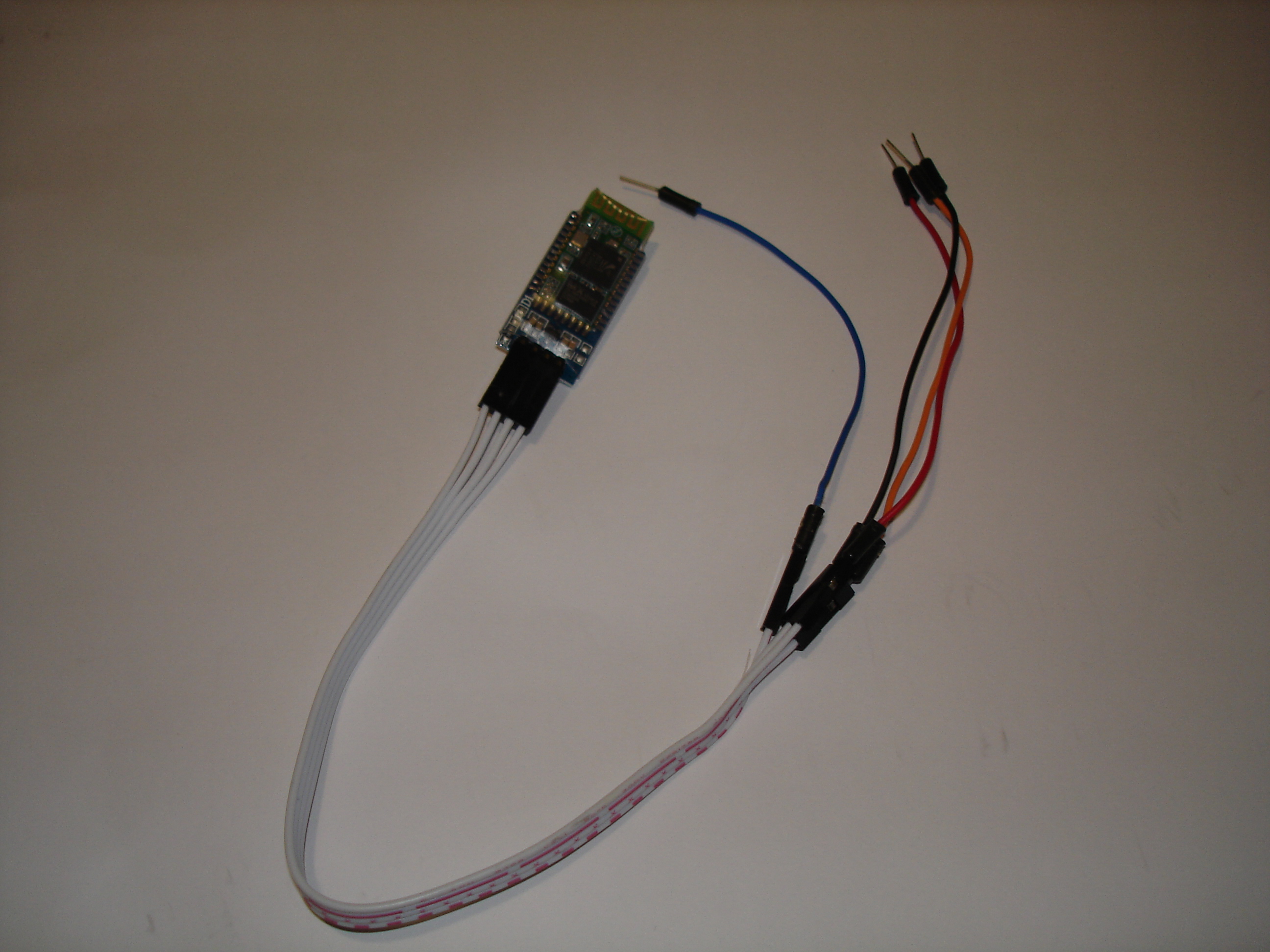
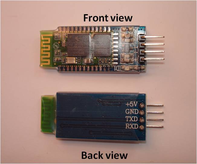
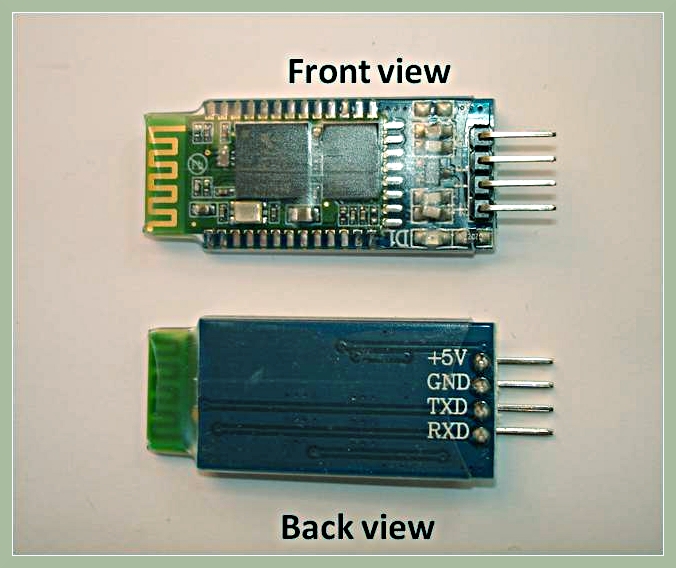
Fig 1: Bluetooth module

This HC-06 Bluetooth module is the most economical and easiest way to go wireless.

This module allows you to wirelessly extend your serial interface, Hence any program running on your Laptop feels its controlling a local serial port (which is over a wireless bluetooth link )

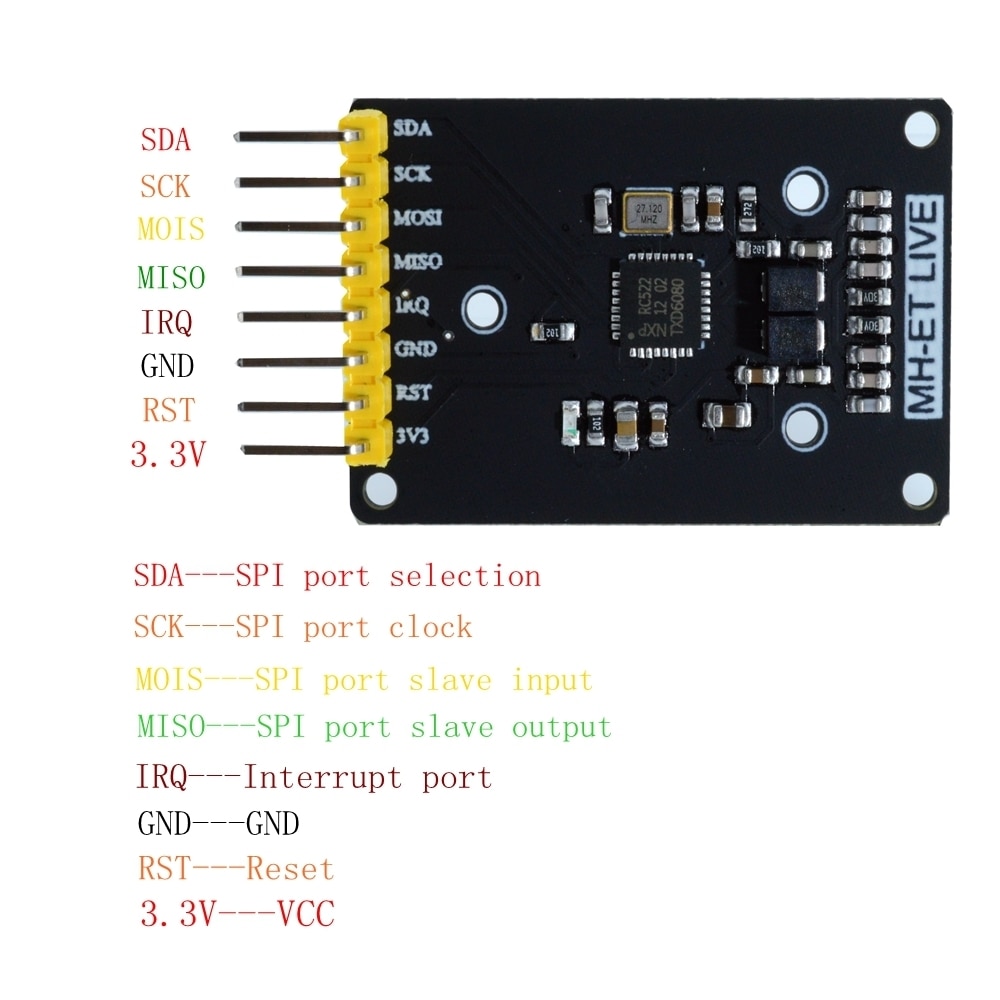
The 4 pins are +5V, GND, TXD, RXD. Supply voltage should be 3.3 - 6 V. Absolute maximum is 7 V.

Default pairing code: 1234

Default baudrate: 9600

HC-04 is almost identical to HC-06. The only difference is that HC-04 is for industry and HC-06 is for civil. Other than that, they are the same. Please refer this HC-04 Datasheet for more technical information.

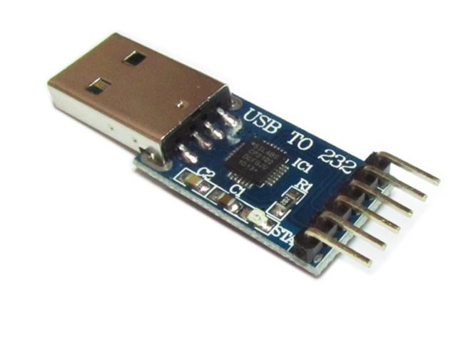
The maximum baudrate can be configured to 1382400bps, but 115200bps is recommended for reliability purposes. The name and paring code can be re-configured by a USB to Serial converter, the steps for the configuration can be found here.

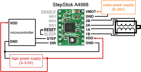
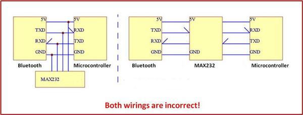
Below shows how the Bluetooth module is connected to the Arduino or other microcontroller device. The Bluetooth module also works in 3.3 V power supply

Fig 2: Bluetooth module wiring

Once the wires are connected, in the computer under the Bluetooth properties, select ‘Add a device’. The default device name of the Bluetooth module is ‘linvor’

Fig3: Detecting the Bluetooth module

Double click ‘linvor’ and select the ‘Hardware’ tab, you can see which COM port the module is connected. In this example, it is connected to COM 21.

Fig4: Finding the COM port associated with the bluetooth module

You may use any terminal programs, or the open source terminal program puTTY. Download it and double click on the putty.exe, select the ‘Serial’ radio button.

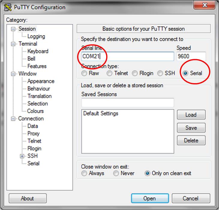
Fig 5: Connecting to the bluetooth module using Putty application

Then type in the COM port number that the Bluetooth device is connecting to. The default baud rate is 9600. Click ‘Open’. And here you go, a new session pops up and if the Bluetooth module’s LED changed from flashing to always on, then it indicates the connection is established.

Test the Bluetooth module : Loopback testing

First test of the bluetooth module is call the the loopback test

  • Wiring the Bluetooth to get power from the Arduino

To wire up the Bluetooth, power up the Arduino board (with usb or other power source), connect the +5 V and GND to the Arduino, then short circuit the rx and tx pin. 

By doing this, you’ll receive exactly what you send.

  • Bluetooth test from PC

In the Bluetooth device properties of your computer, add the Bluetooth device by selecting ‘add a device’.

The default device name is linvor, and default pairing code is 1234, default baud rate 9600.

The device doesn’t need any driver. Please ignore the ‘unknown device warning’ in the windows device manager.

In the Bluetooth connection property, you can found which COM port the Bluetooth module is connected to.

Note: Until now the LED on the Bluetooth module is still flashing. Launch puTTY, type in the correct COM port and start the session. Soon after the session started, the flashing should stop and the LED on the Bluetooth module should stay on, which indicates that the connection has been established. In default setting, puTTY doesn't echo what you type, and whatever you type in puTTY gets sent to the Bluetooth module. So if you can see what you type in the terminal (non-repeated), it means the Bluetooth received the character you typed and sent it back to puTTY.


For advance users who want to customize the settings of the Bluetooth module, see Bluetooth module configurations. However, you are encouraged to skip this and continue to step3 to get your wireless rover working first!


Bluetooth module is not visible to Android phones and Android tablets?
It is reported that Android has some issues with the Bluetooth Serial Port Protocol (SPP). Installing TerminalBT app allows a pairing / connect to the Bluetooth module. This link explains it in a bit more detail.


Slow response in Arduino IDE when Bluetooth is enabled

When the Bluetooth of a laptop is enabled, the Arduino IDE becomes painfully slow and it is unusable. This is due to the auto-scanning COM port feature of the IDE. This link explains how to resolve this problem.


Step3: Combine Bluetooth with Motor Shield

Catalog: 

Price: $23.99

Pages

Zircon - This is a contributing Drupal Theme
WeebPal