Wireless

Image: 

Wifi Datalogger and monitoring system

Description: 

We have built a new version with a better price, you can check it here

Wifi DataLogger with long battery life


Industrial and commercial projects need constant monitoring of sensors and collection of data in a format which is readily accesible and can be visualized with ease. For solving this problem we have developed a Datalogger and monitoring system which works over Wifi.

  The beauty of this system is its entirely self sufficient, Does not need an existing wireless network. It simply creates its own Wifi access point and
the you can connect to it simply with a PC, android or Iphone.


What does this mean:

This means the user is able to monitor the temperature sensors connected to the datalogger in these simple steps

1. Smart phone (iphone, android ) or your PC sees "DATALOGGER" wifi network, simply connect to it.

2. Download the logged data in the format of Excel readable CSV files

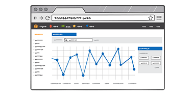
3. See live graphs by clicking following this URL.


This device can be used for monitoring temperature for soil, industrial monitoring systems, vineyards etc. We do provide support to add different type of sensors to cater for other datalogging uses.


What comes with the purchase:
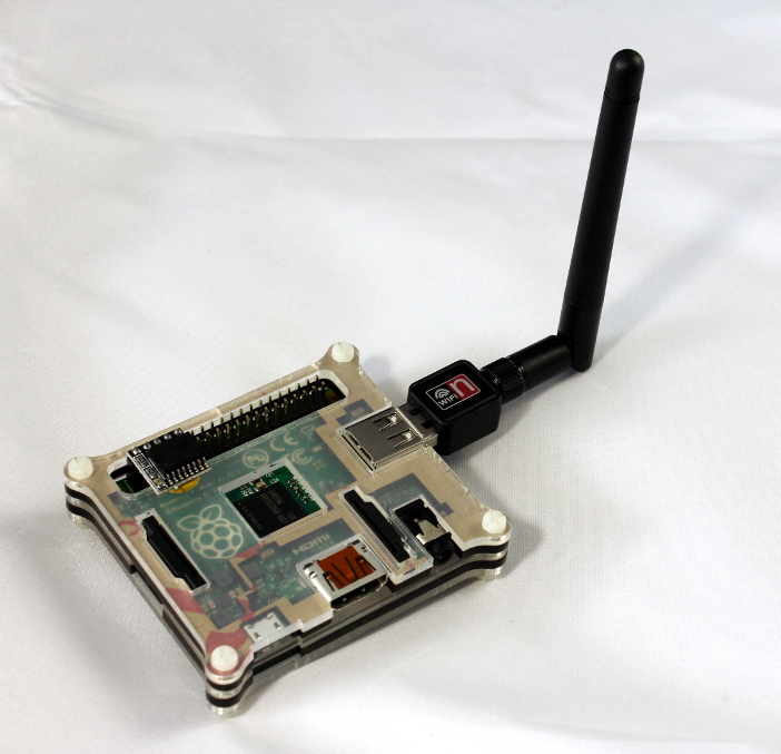
  • Datalogger
  • 2 x Temperature sensors (water proof,  -25 - 125 DegC range)
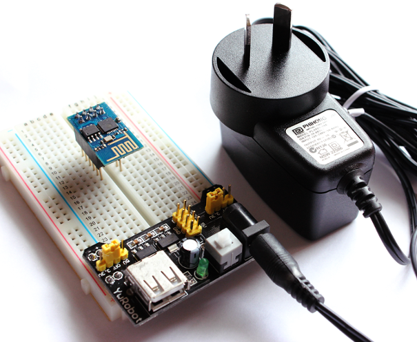
  • 5v Power adapter


FAQ:

1. Can this Datalogger connect to other sensors other than the ones which comes with it ?
A. Yes, we already have support for K type thermocouples ( works upto 500 Deg C ) as well as others, just contact us and post your needs we can get it working for you.

2. Will this sensor work in places with no Wifi coverage?
A. Yes, Since this device creates its own Wifi network, it can work in areas where there is no wifi coverage.

3. How does the graph look like?
A. The graphs would have the same look and feel as this one ( NOTE: For the datalogger the data would be 2 Temperature series lines )

4. Can I see a sample of the Excel readable file which the datalogger creates? 
A. This sample CSV file was created by the logger. You can download it and view it in Excel. ( or openOffice ) 

3. Can I get you to add more temperature sensors of the same type to this logger ?
A. The standard package comes with 2 Temp sensors ( -25 - 125 DegC range),  for sure we can add more sensors to the Logger for a small cost.

4. Does this device need any assembling or is this a plug and play device ?
A. This is a plug and play device with no assembling required. You just have to power it and it should just work out of the box.

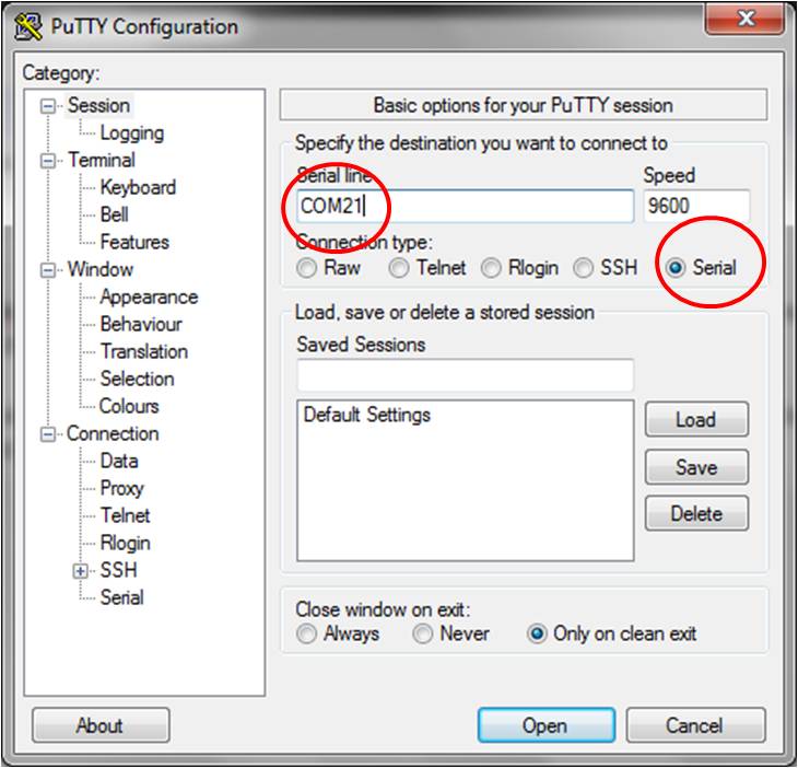
5. How do I view the graphs once the Datalogger is powered up ?
A. From your Mobile/PC connect to the Wifi network called 'DATALOGGER'. Once connected you can view the graphs by
    accessing this link http://192.168.10.1/sensorframework/graph/graph.html

wifi temperature sensor, wifi temperature monitor, wifi temperature monitoring, temperature sensor wifi, home temperature monitor wifi, wifi temperature sensors, wifi temperature probe, remote temperature sensor wifi, temperature alert wifi, wifi sensors temperature, temperature monitor wifi, remote temperature monitor wifi, temperature wifi, wifi home temperature monitoring, arduino wifi temperature sensor, wifi data logger, wifi logger, data logger wifi, wifi temperature logger, temperature logger wifi, wifi temperature data logger, temperature data logger wifi, wifi data loggers, datalogger, wifi thermometer, wifi thermometer sensor, thermometer wifi, thermometer wifi sensor, wifi thermometers, wifi enabled thermometer, wifi thermometer iphone, wireless thermometer wifi, wifi pool thermometer, wifi remote thermometer, thermometer with wifi, data logger, data loggers, data logger software, wireless data logger, current data logger, portable data logger, solar data logger, electrical data logger


Price: $395.00

Wifi weatherstation kit with Live Graphs

Description: 

The devices which connect to internet has been shrinking at very fast pace, Now its got to the size which fits on your fingers and can not only connect to the internet but as also do some sensing.

ESP8266 chipset has made waves since it got introduced, Due to its small size and capablities. This is the first generation of IOT technologies which is going to change the way we live.

We use this powerful tiny module to build a complete WeatherStation kit, which collects Temperature, Humidity and Barometer readings. Not only does it collect the data, It stores it in the cloud for you to watch the data in the form of live Graphs from any device be it your mobile, PC or tablet. Isnt that cool....

With the purchase of the kit we give you a unique key, which is used to provide access to the cloud storage to store it as well as download the data.


Click here to see the Live Demo graph


You can use this kit for many purposes:


                   Fig: Electronic Barometer + Temperature + Humidity sensing


  • Room temperature logging
  • Home Insulation checks
  • Greenhouse monitoring
  • Industrial data logging
  • Recording change of weather in your area and publishing it on the web
  • Add more sensors like power monitoring and make this a multisensor IOT kit

Fig: View Live graphs from anywhere

There is a lot you can do with this powerful combination of low power sensor and cloud access.

The kit comes with complete step by step instructions to buid the kit.

1. The Esp8266 Weatherstation Cloud based Kit

2. Building the kit Weatherstation

3. Optional ESP8266 firware upgrade tutorial

Price: $129.00

esp8266 wifi starter kit

Description: 

Connecting to the internet has not been easier, With the advent of the new IOT ( Internet of things) module ESP8266 its a breeze to connect your microcontroller and

Arduino projects to the internet.

Things you can do with this module:

  • Send you sensor data to server
  • Send an email every time an event occurs, like someone triggering a PIR sensor while you are out on vacation
  • Have an Arduino display what the weather would be like today by getting data from metservices
  • See if your plants need watering by having the Arduino send humidity data through wifi
  • You fill in the rest with your creativity and imagination

ESP8266 specs

Links:

Detailed technical specs and SDK with examples

  • 802.11 b / g / n / d / e / i / k / r support
  • Wi-Fi Direct (P2P) support
  • P2P discovery, P2P group master mode (Group Owner mode), P2P Power Management
  • Infrastructure Network (Infrastructure BSS) station (Station) mode / P2P mode / SoftAP mold
  • hardware acceleratorPre-Certification
    • CCMP (CBC-MAC, counting mode)
    • TKIP (MIC, RC4) o WAPI (SMS4)
    • WEP (RC4)
    • CRC
    • WPA / WPA2 and WPS support
    • Other 802.11i security features:

arduino wifi,wifi network,wi-fi network, esp8266 wifi, esp8266 module,esp8266 wifi module, rs232 to wifi, serial to wifi, wi-fi networking, esp8266 buy, wireless usb, embedded wifi module, module wifi, embedded wlan module, esp8266 serial wifi, usb wireless

What comes as part of the ESP8266 starters kit:


1. Mini Breadboard

2. Breadboard  power supply for providing the 3.3V required by ESP8266

3. ESP8266 module


4. ESP8266 headers, without which you cannot mount them on the breadboard

5. 9V Power Adapter for the breadboard power supply

Complete kit:


Instructions to talking with the ESP8266 with FTDI USB serial or via Arduino:

https://maker.pro/education/how-to-connect-a-raspberry-pi-to-a-laptop-display


FAQ

1. Why is the 9v adapter needed? Can't I power with Arduino's 5V?

A. The Esp8266 can draw upwards of 300mAmps, The Arduino power supply would struggle to power the ESP and the Arduino and cause brownout errors. For this reason having a separate power adapter helps.

    Price: $39.99

    Arduino GSM Module SIM900

    Description: 

    aeProduct.getSubject()

    SIM900 Quad-band GSM GPRS Development Board for Arduino Antenna

    Note:The SIM900 Board Input is 5-26V  2A,We Recommended current is more than 9V 2A. Ensure your SIM card is not locked GPRS Communication baud rate is 19200 BPS 8-N-1

    The GPRS module is based on SIM900 module from SIMCOM and compatible with Arduino and its clones. The GPRS module provides you a way to communicate using the GSM cell phone network. The module allows you to achieve SMS, MMS, GPRS and Audio via UART by sending AT commands (GSM 07.07 ,07.05 and SIMCOM enhanced AT Commands). The module also has the 12 GPIOs, 2 PWMs and an ADC of the SIM900 module(They are all 2V8 logic) present onboard.

    Features

    •  Quad-Band 850 / 900/ 1800 / 1900 MHz - would work on GSM networks in all countries   across the world.
    •  GPRS multi-slot class 10/8
    •  GPRS mobile station class B
    •  Compliant to GSM phase 2/2+
    •  Class 4 (2 W @ 850 / 900 MHz)
    •  Class 1 (1 W @ 1800 / 1900MHz)
    •  Control via AT commands - Standard Commands: GSM 07.07 & 07.05 | Enhanced   Commands: SIMCOM AT Commands.
    •  Short Message Service - so that you can send small amounts of data over the network   (ASCII or raw hexadecimal).
    •  Embedded TCP/UDP stack - allows you to upload data to a web server.
    •  RTC supported.
    •  Selectable serial port.
    •  Speaker and Headphone jacks
    •  Low power consumption - 1.5mA(sleep mode)
    •  Industrial Temperature Range - -40°C to +85 °C

    Specs:


    •  The factory default setting for the GPRS Shield UART is 19200 bps 8-N-1. (Can be changed   using AT commands).
    •  Power select - select the power supply for GPRS shield(external power or 5v of arduino)
    •  Power jack - connected to external 4.8~5VDC power supply
    •  Antenna interface - connected to external antenna
    •  Serial port select - select either software serial port or hareware serial port to be connected    to GPRS Shield
    •  Hardware Serial - D0/D1 of Arduino
    •  Software serial - D7/D8 of Arduino
    •  Status LED - tell whether the power of SIM900 is on
    •  Net light - tell the status about SIM900 linking to the net
    •  UART of SIM900 - UART pins breakout of SIM900
    •  Microphone - to answer the phone call
    •  Speaker - to answer the phone call
    •  GPIO,PWM and ADC of SIM900 - GPIO,PWM and ADC pins breakout of SIM900
    •  Power key - power up and down for SIM900
    • Dimensions: 71.4mm X 66.0mm X1.6mm

    aeProduct.getSubject()
    Specifications:

    Application Ideas:

    · M2M (Machine 2 Machine) Applicatoions.
    · Remote control of appliances.
    · Remote Weather station or a Wireless Sensor Network.
    · Vehicle Tracking System with a GPS module.

    SIM900 Arduino library with examples:

    http://www.hobbyist.co.nz/sites/default/files/sim900/GSM_GPRS_GPS_IDE100_v307_1.zip

    Wiring to Arduino

    If you want the arduino to send SMS or connect to the GPRS network, this is the module for you. It can be used for applications like vehicle tracking, weather baloonsor even sending data from your weatherstation to your mobile as a SMS.

    Arduino gsm, arduino gprs, modem gsm, arduino sim900,gsm modul, gsm tutorial, gprs modem, arduino sms,sms modem, arduino web, arduino internet, usb gsm,sms shield, arduino 3g, arduino sim

    Catalog: 

    Price: $79.00

    WiFi Switch: Turn your kettle on from your mobile

    Description: 

    There isn't a cleaner way to control something through the internet than using this WiFi Universal Power Adapter. It's super easy to setup and use. Think off things you can control on/off by your cellphone, or computer , usage of this plug is only limited by your imagination.

    Plug in the device you want into this socket and you are free to turn it ON from anywhere with your phone.

    The app is designed to allow adding multiple sockets in your house and label them "Kettle", "Lights", "Heater" etc 

    Effectively with this device you have the control of you entire home right in your pocket.

    Control web, server control, web based,control application, iot, internet of things, power ethernet, wireless switch, power outlet control, phone controlled, app controlled, home automation, ip power, light remote, control switch, switch internet, pdu, remote pdu, remote outlet, network controlled, power outlet control 

    Catalog: 

    Price: $59.99

    Bluetooth Module (Master)

    Description: 

    Bluetooth Module (Master):

    This is the HC-06 Bluetooth module, master. It can talk to the HC-06 Bluetooth module, device.

    Please note:

    • HC-06 master can only connect to HC-06 device.
    • The role of a HC-06 Bluetooth module master and a HC-06 Bluetooth device cannot be interchanged, its defifined in its firmware, which is proprietary.
    • The name of the master module cannot be changed, and other commands are the same as the device module.

    Once the master detects a slave module with the same paring code, it will establish the connection. and next time, even after power down, once the master module detect the same slave module, it will automatically connect to it even other slave modules are also nearby. The master module recognizes that specific slave module through it's MAC number. A master module that is mated with a slave module has a slow flashing LED. Once connection established, its LED stays on. To reset the MAC number, press the button on the master module, or give the 'key/wake' pin a logic high impulse. Once it's reset, and if there are more multiple slave modules in the vicinity with the same paring code, the master module will randomly pick one to connect, and will again, lock into that module until the reset button is pressed.


    Catalog: 

    Price: $25.99

    Bluetooth Module (Device)

    Description: 

    Bluetooth Module:

    Fig 1: Bluetooth module

    This HC-06 Bluetooth module is the most economical and easiest way to go wireless.

    This module allows you to wirelessly extend your serial interface, Hence any program running on your Laptop feels its controlling a local serial port (which is over a wireless bluetooth link )

    The 4 pins are +5V, GND, TXD, RXD. Supply voltage should be 3.3 - 6 V. Absolute maximum is 7 V.

    Default pairing code: 1234

    Default baudrate: 9600

    HC-04 is almost identical to HC-06. The only difference is that HC-04 is for industry and HC-06 is for civil. Other than that, they are the same. Please refer this HC-04 Datasheet for more technical information.

    The maximum baudrate can be configured to 1382400bps, but 115200bps is recommended for reliability purposes. The name and paring code can be re-configured by a USB to Serial converter, the steps for the configuration can be found here.

    Below shows how the Bluetooth module is connected to the Arduino or other microcontroller device. The Bluetooth module also works in 3.3 V power supply

    Fig 2: Bluetooth module wiring

    Once the wires are connected, in the computer under the Bluetooth properties, select ‘Add a device’. The default device name of the Bluetooth module is ‘linvor’

    Fig3: Detecting the Bluetooth module

    Double click ‘linvor’ and select the ‘Hardware’ tab, you can see which COM port the module is connected. In this example, it is connected to COM 21.

    Fig4: Finding the COM port associated with the bluetooth module

    You may use any terminal programs, or the open source terminal program puTTY. Download it and double click on the putty.exe, select the ‘Serial’ radio button.

    Fig 5: Connecting to the bluetooth module using Putty application

    Then type in the COM port number that the Bluetooth device is connecting to. The default baud rate is 9600. Click ‘Open’. And here you go, a new session pops up and if the Bluetooth module’s LED changed from flashing to always on, then it indicates the connection is established.

    Test the Bluetooth module : Loopback testing

    First test of the bluetooth module is call the the loopback test

    • Wiring the Bluetooth to get power from the Arduino

    To wire up the Bluetooth, power up the Arduino board (with usb or other power source), connect the +5 V and GND to the Arduino, then short circuit the rx and tx pin. 

    By doing this, you’ll receive exactly what you send.

    • Bluetooth test from PC

    In the Bluetooth device properties of your computer, add the Bluetooth device by selecting ‘add a device’.

    The default device name is linvor, and default pairing code is 1234, default baud rate 9600.

    The device doesn’t need any driver. Please ignore the ‘unknown device warning’ in the windows device manager.

    In the Bluetooth connection property, you can found which COM port the Bluetooth module is connected to.

    Note: Until now the LED on the Bluetooth module is still flashing. Launch puTTY, type in the correct COM port and start the session. Soon after the session started, the flashing should stop and the LED on the Bluetooth module should stay on, which indicates that the connection has been established. In default setting, puTTY doesn't echo what you type, and whatever you type in puTTY gets sent to the Bluetooth module. So if you can see what you type in the terminal (non-repeated), it means the Bluetooth received the character you typed and sent it back to puTTY.


    For advance users who want to customize the settings of the Bluetooth module, see Bluetooth module configurations. However, you are encouraged to skip this and continue to step3 to get your wireless rover working first!


    Bluetooth module is not visible to Android phones and Android tablets?
    It is reported that Android has some issues with the Bluetooth Serial Port Protocol (SPP). Installing TerminalBT app allows a pairing / connect to the Bluetooth module. This link explains it in a bit more detail.


    Slow response in Arduino IDE when Bluetooth is enabled

    When the Bluetooth of a laptop is enabled, the Arduino IDE becomes painfully slow and it is unusable. This is due to the auto-scanning COM port feature of the IDE. This link explains how to resolve this problem.


    Step3: Combine Bluetooth with Motor Shield

    Catalog: 

    Price: $23.99
    Zircon - This is a contributing Drupal Theme
    WeebPal