What is a Arduino Motorshield?
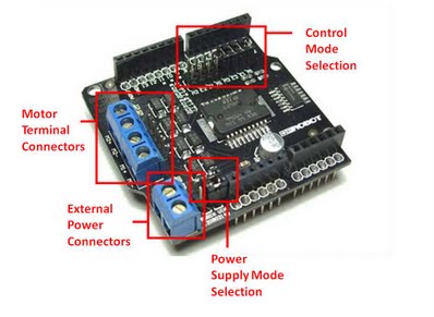
This Arduino Motor Shield is built upon the L298 Dual channel H-bridge IC, with a maximum DC current of 2 A for each channel. This current rating is sufficient for most home made medium size robots. It has 3 different power operating modes based on the positions of the jumpers. When plugged into an Arduino board, the Power Supply Mode Selection jumper allows you to choose how the motor shield and the Arduino are powered.
Modes of operation:
Mode 1 : PWRIN & VIN
This mode is to short both the PWRIN and VIN, which is the most commonly used configuration.

In this mode only one power source is needed to connect to the Motor Shield, which also supplies power to the Arduino underneath. The power source should be kept between 6.5 - 12 V.
Mode 2: Vin only
In this mode, both of the jumpers are on VIN as shown in the figure below.

This mode actually lets the Motor Shield to get the power from the Arduino, which means the Arduino board has to be powered up by a center-positive power jack. Again, the voltage level should be 6.5 - 12 V.
Mode 3: PWRIN only
In some applications you may wish to keep the power sources of the Motor Shield and the Arduino separate. This requires both jumpers to sit on the PWRIN as shown in the figure below.
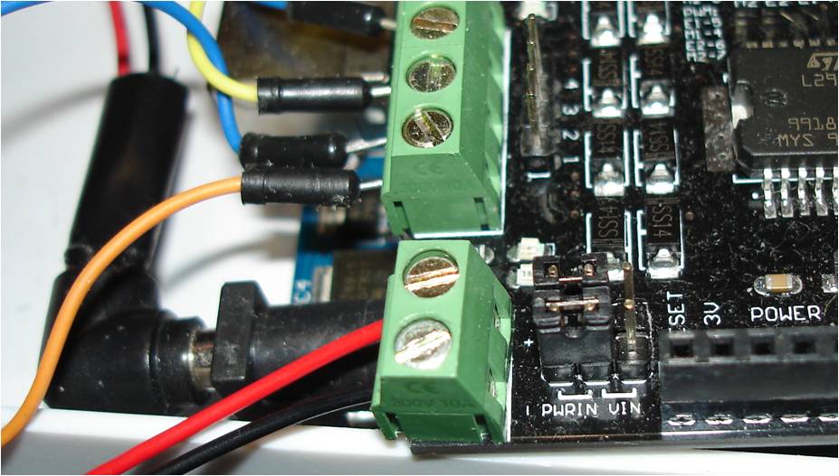
A good reason to keep the power sources separate is when the Motor Shield needs to supply large current and there are substantial noise while controlling the current through PWM. If both the analog and the digital share the same power source, in the event of current surge, the voltage level can drop suddenly and hence the microcontroller can make wrong decisions. Better digital signal integrity is obtained if the analog and digital power supply are kept separate. But remember, they should have a common ground. In this mode, the voltage range to the Motor Shield is 4.8 - 24 V, and to the Arduino is 6.5-12V.

After selecting the power mode, the rest of the work is quite straightforward and pretty much self-explanatory. Connect the first motor to M1+ and M1- and the second motor to M2+ and M2-, the motor can be controlled through PWM (pulse width modulation) or PLL (Phase locked loop) by placing the jumpers in the Control Mode Selection.
Programming the Arduino
Once all the wires are hooked up, you are ready to download the example code ( provided on purchase ) to test the Motor Shield. The code should work on any Arduino compatible boards, and in particular we have tested it on Arduino Duemilanove 2009 and Arduino Mega 1280. Make sure you have your external power source connected, because the USB cable alone will be most likely not able to supply the current for the DC motors. From Arduino IDE, after plugging in the USB cable, double check if the correct board is selected from Tools -> Boards, and the correct Serial port is selected from Tools -> Serial port. Upload the program once you are happy with the settings. Open the serial monitor, press ‘e’ and ‘Enter’ on the keyboard, your motors should be turning and the serial monitor should display “Go!!”.

How to control the robot
If that’s the case, congratulations, you have got the Motor Shield going! The ‘s’, ‘f’,’c’ keys control the motors to turn in different directions, and the ‘d’ key is to stop. Play with it, the direction of the motor may appear opposite to what you want. If this is the case, you may either need to swap the polarity of the motor or swap the High and Low logic in the code.
If you still need some more references for the Motor Shield, you may download the manual.
Step2: Test the Bluetooth module