Arduino

What is an Arduino?
Its a mini computer, which you can program using C. The learning curve is small and one can easily get the first working program running in a matter of minutes. ( A variety of code examples are included in the CD)

Image: 

Arduino Experimenters Kit : Sense and control just about anything

Description: 

Arduino is a versatile platform which is easy to program and do simple to complex tasks with the help of open source libraries.

Arduino board does not come with any sensors, this kitset bridges the gap and allows the keen Arduino experimenter to have access to an 
array of sensors and controls to build many great projects.

One common problem faced with interfacing hardware to arduino is lack of readily available examples to get it going, We provide a complete library (on purchase) for 
all the sensors to make it easy for the user to get them going and move on to building interesting projects, Instead of having to struggle to find the right library for each sensor.

This would be an ideal gift for any tinkerer who like to play with electronics and programming. This kit would offer hours of excitement, experimentation and
learning and be a stepping stone to move on to build bigger things and solve problems.

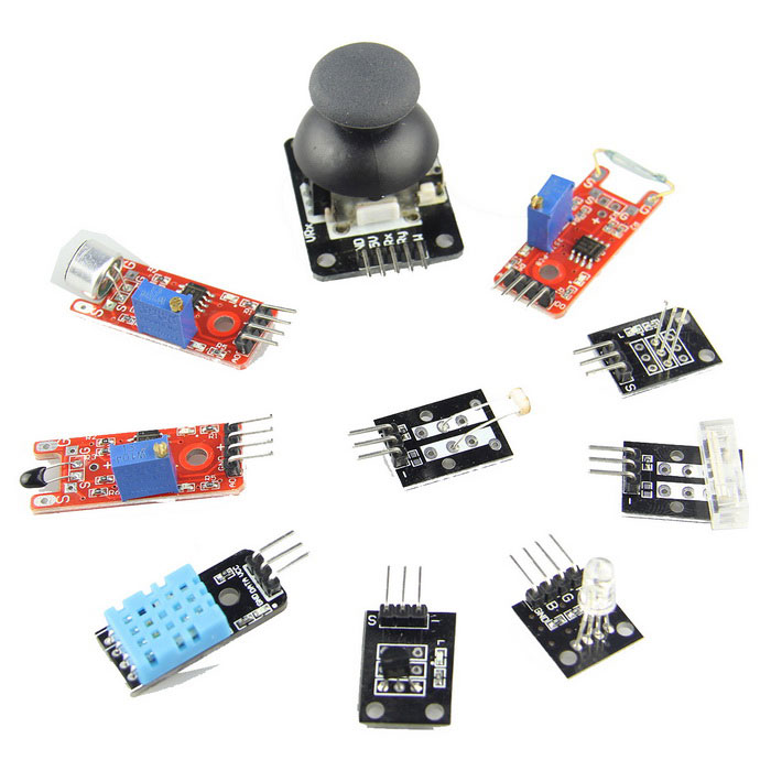
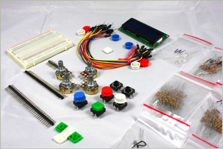
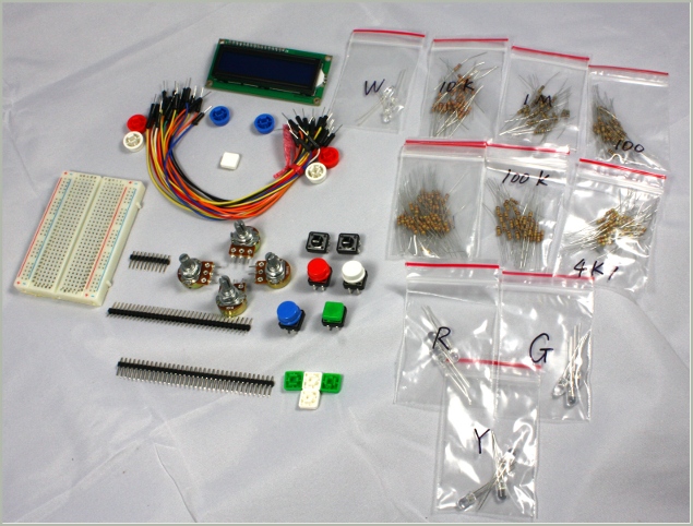
This versatile kit for the Arduino comes with 30+ sensors which can be used for carrying out a variety of experiments. They have easy to use connectors which makes interfacing to the Arduino straight forward.

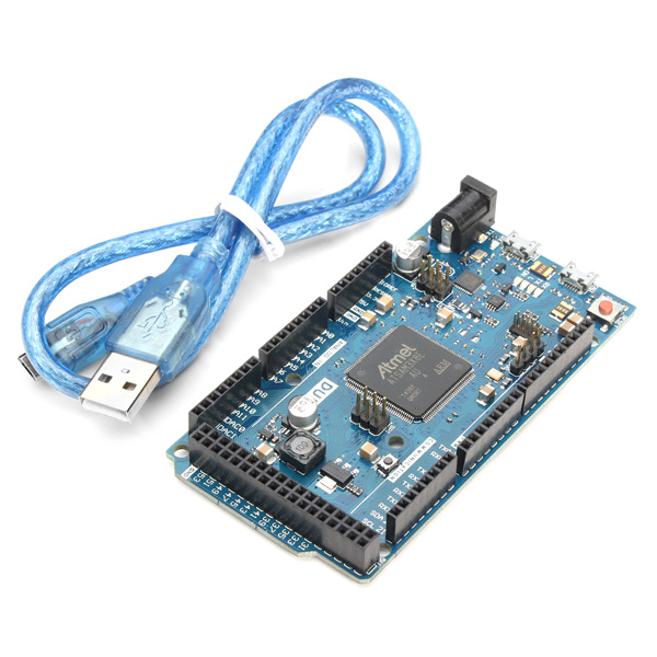
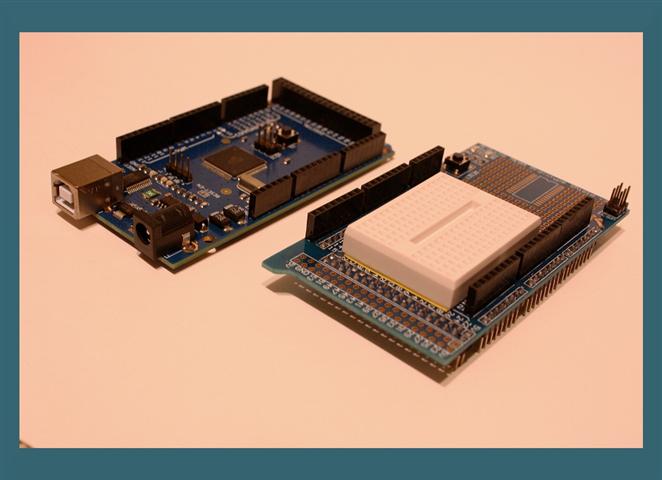
This kit comes with an Arduino Uno compatible board along with all the below listed sensors:


Joystick

The analogue joystick has two axis and 2 x 10k potentiometers with a push button action. Connector pins are described on the PCB. Included with the module is a push-on operating knob.


Relay

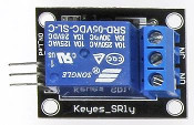
This single relay module can be connected directly to an Arduino and requires a 5VDC supply for operation. The input is identified with an 'S'. The relay has one change over contact and can switch resistive loads up to 10A at 250VAC, and up to 10A at 30VDC maximum. Interference suppression will need to be provided.


Sensitive Microphone

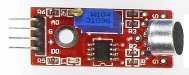
This features a high-sensitivity large format electret capsule and a potentiometer which allows adjustment of the sound level. The output D0 (active high) is switched when the sound level exceeds a preset level. The analogue output is available at pin A0.


Small Microphone

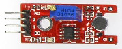
Except for the smaller size of the capsule and lower sensitivity, this module is identical to the Sensitive Microphone above.


IR Light Reflection Switch

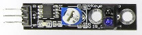
This switch is useful for avoiding obstacles or getting a model to move around the floor following a line. An obstacle in front of the sender/receive diodes will cause the output pin to be pulled low (active low). The detection range is approximately up to 1cm and a potentiometer allows the sensivity to be adjusted.


IR Reflection Sensor

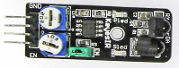
Also useful for applications where obstacles need to be avoided. When an obstacle is detected by this unit the output pin becomes low (active low). This has improved distance sensitivity as it can detect objects up to around 7cm, with the sensivity adjustable through a potentiometer. An enable (EN) jumper can be installed to allow continuous operation. With the jumper absent it allows an external logic signal to be applied at the jumper to switch the detector on and off. This is active low.


Flame Sensor

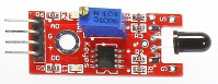
With a typical spectral sensitivity range of 720-1100nm at an angle of 60 degrees, this module allows flames to be detected and is optimised to detect emissions from naked flames. When a flame is detected, D0 goes high (active high). The detection threshold can be adjusted with the potentiometer. The analogue output signal is accessible via pin A0.


Linear Hall Sensor

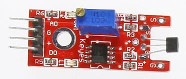
This detects the presence of a magnetic field. When such a field is present, D0 will go high (active high). The point at which this happens depends on factors such as field strength, polarity, and the position of the magnet relative to the sensor, and the sensivity adjustment of the potentiometer. The analogue output signal is available at pin A0.


Touch Sensitive Switch

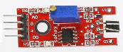
Touching the sensor pin produces an output at D0 and is active high. The output includes 50Hz mains induced signals so it's not clean. The sensitivity can be adjusted with a potentiometer and the analog output signal is available at pin A0.


Digital Temperature Sensor

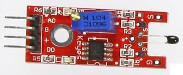
This temperature sensor uses a NTC style thermistor. A potentiometer allows a temperature threshold to be preset that causes D0 to switch high when that temperature is reached. The analog output from the sensor is accessible at pin A0.


Buzzer

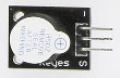
It's all in the name really, this module is an electronic buzzer. Take care when hooking this up as 5VDC needs to be supplied on the '-' pin while ground is on the pin marked 'S'. It typically operates at a frequency of 4kHz at a minimum of 80dB and typically draws 5mA at 5VDC.

This buzzer looks very similar to the passive buzzer below but can be identified as the buzzer itself is a little taller than the passive version.


Passive Buzzer

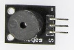
This buzzer, or mini loudspeaker, is slightly shorter than the buzzer above. It has 16 ohm impedence and maximum continuous current through the speaker coil is about 25mA. The outer two pins '-' and 'S' connect to the speaker and is not polarity sensitive.


RGB LED

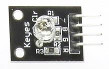
This clear lense colour LED uses a 150ohm series resistor and can be used on 5VDC. The '-' is the common cathode but we aware that the labelling on the PCB is incorrect. Red and Blue are actually the other way around.


SMD LED

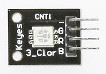
There's no series resistor supplied with this RGB LED, so you'll need to provide your own. A 220ohm resistor would be suitable. The '-' pin indicates a common cathode, but as before the PCB labelling is incorrect. This time however the Green and Red connections are switched.


Bi-colour 5mm LED

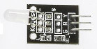
With this two colour LED, '-' represents the common cathode on the PCB. The pin marked 'R' is for the Red anode and the 'S' pin is for the Green anode. As there's no series resistor provided you'll need to provide one, around 220ohms.


Bi-colour 3mm LED

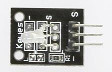
Like the 5mm LED above, the '-' on the PCB indicates the common cathode. The middle pin is the anode for the Red LED and the 'S' pin for the Green LED. As there's no series resistor provided you'll need to provide one, around 220ohms.


Reed Switch

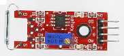
In addition to a digital output on D0, this reed switch also offers an analogue output on A0. Ground can be found at the 'G' pin while '+' requires 5VDC. The potentiometer supplied is used as a pull up resistor.


Mini Reed Switch

The outer two pins on the three pin male connector join up to the reed switch. It is normally open and requires a magnetic field to close the contacts. A 10k ohm resistor is onboard and is connected between the centre pin and the 'S' pin. This can be used as a pull up or pull down resistor.


Heartbeat Sensor

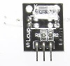
This neat device can be used to read a person's pulse when a fingertip is placed between the Infrared LED and the photo transistor. External circuitry is needed. 5VDC needs to be supplied to the centre pin, ground connected to the pin marked '-' and the photo transistor signal is available at the 'S' pin (this has its own pull up resistor). A 300ohm resistor for the Infrared LED is included.


7 Colour Flashing LED

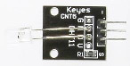
This clear lense LED runs directly from 5VDC and cycles automatically through a seven colour sequence. 5VDC needs to be connected to the 'S' pin and ground on the centre pin.


Laser Emitter

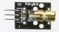
The laser module has a wavelength of 650nm in the red colour spectrum. 5VDC can be connected directly to the 'S' pin and ground to the '-' pin.


Push Button Switch

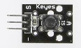
A 10k ohm resistor links the centre pin and the pin marked 'S' and this can be used as a pull down or pull up resistor. The two outer pins connect to the push button. There are various button libraries available for the Arduino that can be used with this module.


Shock, Rolling Ball Type Tilt Switch

The switch contacts are available on the two outer pins, 'S' and '-'. A 10k ohm resistor links the centre and 'S' pins and can be used as a pull down or pull up resistor.


Rotary Encoder

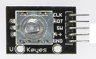
This encoder is useful for making an electronic potentiometer. Pin indentification markings are on the PCB.


Light Cups

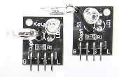
Supplied as a pair, these modules feature a mercury tilt switch and transparent red LEDs. The LED cathode and one terminal of the switch is available at the 'G' pin. The other side of the switch is available at the 'S' pin, and 'L' connects to the LED anode (a series resistor is not provided so a 220 ohm resistor will need to be connected up). The '+' pin connects to a 10k ohm pull up resisitor connected to the 'S' pin of the switch.


Tilt Switch

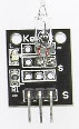
Depending on the altitude this sensor is positioned at, the mercury tilt switch will make or break a connection.


Rolling Ball Tilt Switch

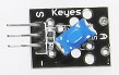
Depending on your application, the built-in 10k ohm resistor connected between the middle and 'S' pins can be used for pull down or pull up use. The outer two pins are for the switch contacts which have a maximum switching load of 50mA at 12VDC.


Photoresistor

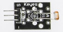
The photoresistor, also known as a Light Dependent Resistor (LDR), determines darkness when the resistance is over 20M ohm, and light at less than 80 ohms. The two outside pins are to be used. There is a 10k ohm resistor on the module between the middle and 'S' pins which simplifies the construction of a measurement bridge circuit.


Temperature and Humidity

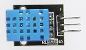
The popular DHT11 sensor allows reading of temperature and humidity. It can sense temperature in the 0-50 degrees celcius range (+/- 2%) and relative humidity in the 20-95% (+/- 5%). It operates on a supply voltage of 3VDC to 5.5VDC and features a built-in 10k ohm pull up resistor. For use with the Arduino DHT.h library.


Analogue Hall Sensor Switch

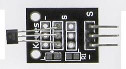
This module features either a 44E311, 3144EUA-S, 3144LUA-S or 49E504BG sensor and has an LED and resistor. When a magnetic field is detected the LED switches on. Ground is indicated by a '-' on the PCB, signal on the 'S' pin and 5VDC on the centre pin.


Hall Magnetic Module

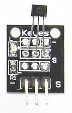
A hall effect sensor module featuring an analogue output signal. The output is available on the pin indicated by 'S', ground on the pin indicated by '-' and 5VDC supply on the middle pin.


Temperature Sensor

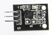
The DS18B20 is a one wire digital temperature sensor with a range of -55 to +125 degrees celcius. Depending on the program, it has a resolution of 9-12 bits with an accuracy of 0.5 degrees celcius. A 4.7k ohm pull up resistor is included on the bus line. Extra sensors can be added to the bus and individually addressed. Only one pull up resistor should be connected to the bus, no matter how many sensors of this kind are used together.


Analogue Temperature Sensor

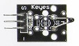
An NTC temperature sensor. The sensor resistance is approximately 10k ohm when at room temperature and the output can be accessed via the two outer pins. A fixed 10k ohm resistor connected between the middle and 'S' pins is included which simplifies the construction of a measurement bridge circuit. Like the DS18B20 digital sensor above, it shares the same temperature range and accuracy.


IR Emitter

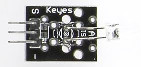
If you want to create your own IR remote control then you will find this emitter useful. Ground is available at the '-' pin, 'S' is the data in while the middle pin is 5VDC supply.


IR Receiver

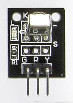
This sensor is the 1838 type and is for use with 38kHz IR signals. It works on a supply voltage of 2.7V to 5.5V, 37.9kHz frequency, with a typical range of 18m and a receiving angle of 90 degrees. A useful library for this is available at https://github.com/shirriff/Arduino-IRremote.


Tap Module

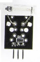
This module senses vibrations. The momentary switch contacts are available at the outer two pins.


Light Blocking Sensor

A slotted light barrier. The middle pin requires +5VDC supply and ground is available at '-'  with the output signal available on the remaining pin and has a 10k ohm pull up resistor connected to +5VDC.

Catalog: 

Price: $79.00

Arduino Due

Description: 

The Due is Arduino's first ARM-based Arduino development board. This board is based on a powerful 32bit CortexM3 ARM microcontroller made programmable through the familiar Arduino IDE. It increases the computing power available to Arduino users keeping the language as compatible as possible so that many programs will be migrated in a matter of minutes!

The Arduino Due has 54 digital input/output pins (of which 12 can be used as PWM outputs), 12 analog inputs, 4 UARTs (hardware serial ports), an 84 MHz clock, a USB-OTG capable connection, 2 DAC (digital to analog), 2 TWI, a power jack, an SPI header, a JTAG header, a reset button and an erase button. There are also some cool features like DACs, Audio, DMA , an experimental multi tasking library and more.

To compile code for the ARM processor, you'll need the latest version of the Arduino IDE: v1.5 (After a period of testing and debugging this will replace the 1.0.1 IDE altogether)

Warning: Unlike other Arduino boards, the Arduino Due board runs at 3.3V. The maximum voltage that the I/O pins can tolerate is 3.3V. Providing higher voltages, like 5V to an I/O pin could damage the board.

Because of the limitations of system voltage imposed by the Atmel SAM3X8E, Arduino shields that are based on the 5v models won't work properly. All the shields that fully implement the Arduino R3 layout are compatible straight away (like the Arduino WiFi shield and Ethernet Shield) but other shields might not be compatible. Be careful when you're plugging stuff in!


*This board is an Arduino Due compatible

Features:

  • Microcontroller: AT91SAM3X8E
  • Operating Voltage: 3.3V
  • Recommended Input Voltage: 7-12V
  • Min-Max Input Voltage: 6-20V
  • Digital I/O Pins: 54 (of which 12 provide PWM output)
  • Analog Input Pins: 12
  • Analog Outputs Pins: 2
  • Total DC Output Current on all I/O lines: 130 mA
  • DC Current for 3.3V Pin: 800 mA
  • DC Current for 5V Pin: 800 mA
  • Flash Memory: 512 KB all available for the user applications
  • SRAM: 96 KB (two banks: 64KB and 32KB)
  • Clock Speed: 84 MHz

Arduino Due (Arm Core) benefits over other Arduinos

The Due has a 32-bit ARM core that can outperform typical 8-bit microcontroller boards. The most significant differences are:

  • A 32-bit core, that allows operations on 4 bytes wide data within a single CPU clock. 
  • CPU Clock at 84Mhz.
  • 96 KBytes of SRAM.
  • 512 KBytes of Flash memory for code.
  • a DMA controller, that can relieve the CPU from doing memory intensive tasks.

Catalog: 

Price: $89.99

Arduino Pro Mini

Description: 

Best board for low power projects, which needs to fit into a small space.

This board comes with Arduino bootloader already flashed, you just need to
hook it to a usb to serial converter and start downloading your code.

This board is based on the opensource Arduino spec, uses ATmega328P at its core. This is a Arduino clone which is perfectly compatible with the Arduino IDE and examples provided in it.

Arduino compatible technical specs:
 

  • 20 digital input/output port RX and TX, D2 ~ D13, A0 ~ A5
  • 8 analog input port A0 ~ A7
  • 1 to the TTL level a serial port to send and receive port RX/TX
  • 6  PWM port, D3, D5, D6, D9, D10, D11
  • Using Atmel Atmega328P - AU microcontroller
  • Support serial download
  • Support external 5 V ~ 12 V dc power supply
  • Support the 12 v and the following batteries
  • 16 MHZ/8MHZ clock frequency
  • Size: 33.3 * 18 (mm)

Programming Arduino Pro mini:

One of the common issues faced when programming Arduino Pro mini is that the dowload fails. The reason for the same is Pro Mini needs to be reset before downloading the code.

The best way to do it is to press the reset button on the Arduino Pro mini 1-2 secs before you press download from the Arduino IDE, this should fix the problem for good.

Catalog: 

Price: $16.99

Arduino Starter Kit - Tutorials included

Description: 

This starter kit comes with all the bits you need to create interesting arduino projects and

to explore the potential of the arduino platform.


 The kit comes with the following:

  • Batch of 20+ multicoloured wires

  • Breadboard

  • 16x2 Blue backlight LCD module

  • 3 Potentiometer ( to create analog sensors and joysticks )

  • 6 Switches

  • Red, Green, Yellow, Pure White led packs ( 12 LED's )

  • 6 packs of Resistors

  • 6 multicolor switch caps to make a colourful interface for the kit

  • Arduino Uno compatible

  • USB cable


Things you can do with this kit:

- LCD menu controlled by potentiometer Joystick

- Lights which dance to music or to timed patterns

- LED Cube

- LCD ping pong with touchbutton interface


and many more only limited by your imagination...


Things to do with the starter kit:
1. Building a traffic light with Arduino + LED's

https://arduinomylifeup.com/arduino-traffic-light-project/


Add on challenge: Modify the above code to support a pedestrian press button for crossing

2. Building a hit counter using Arduino + LCD + Click switch


Add on challenge: Modify the above code to make a stop watch

3. Building an interactive jumping man Game using Arduino + LCD + Switch

http://www.instructables.com/id/Arduino-LCD-Game/?ALLSTEPS


Add on: Change the moving blocks in the above game to make pacman style monsters

4. 2 player pingpong game using Arduino + 2 x Potentiometer as joystick


Arduino, arduino starter kit, practical arduino, for arduino, how to arduino, arduino is, arduino and, with arduino,starter kit, projects for arduino, projects on arduino, arduino project, uno arduino, arduino uno

Catalog: 

Price: $59.90

Arduino Nano 3.0

Description: 

It has similar functionality to the Arduino Uno, but in a DIP module package and works with a Mini-B USB cable. The Mini-B USB cable is included.

This board is a Arduino clone which is perfectly compatible with the Arduino IDE and examples provided in it.

Technical specifications of the Arduino Nano board

The technical specifications of the Arduino Nano board are as follows:

  • Microcontroller ATmega328
  • Operating Voltage (logic level): 5 V
  • Input Voltage (recommended): 7-12 V
  • Input Voltage (limits): 6-20 V
  • Digital I/O Pins : 14 (of which 6 provide PWM output)
  • Analog Input Pins: 8
  • DC Current per I/O Pin: 40 mA
  • Flash Memory 32 KB (ATmega328) of which 2 KB used by bootloader
  • SRAM: 2 KB (ATmega328)
  • EEPROM: 1 KB (ATmega328)
  • Clock Speed: 16 MHz
  • Dimensions: 0.73" x 1.70"

Powering the Arduino Nano

The Arduino Nano can be powered via the Mini-B USB connection, 6-20V unregulated external power supply (pin 30), or 5V regulated external power supply (pin 27). The power source is automatically selected to the highest voltage source.

Catalog: 

Price: $29.99

Arduino Mega 1280 ProtoShield Combo

Description: 

This is the Mega version of the ProtoShield combo. The Mega 1280 has much more capability than the Arduino Duemilanove 2009, it has got more on board memory, more processing power and more I/Os. With this kit, prototyping with the Mega will never be easier, especially for beginners! Circuits can be tested on the breadboard, once they are working, they can be soldered onto the ProtoShield to be made permanent.

This kit includes:
- Arduino Mega 1280 
- USB cable (not shown in photo)
- Mega ProtoShield
- Mini breadboard
- IDE with development software for Windows, Linux, Mac and lots of code examples
- A bunch of breadboard wires (not shown in photo)

The Arduino Mega clone specs :

  •   Powerful ATmega1280 Processor:
  •   128KB of Flash, 8KB RAM, 4KB EEPROM
  •   53 digital I/O
  •   14 PWM Channels
  •   16 Analog Inputs
  •   4 UART Channels
  •   SPI Interface
  •   I2C Interface
  •   USB interface (Used for power supply + Programming )

A Easy start to your first microcontroller project...

Free source code and example available at:

http://www.arduino.cc/

Look here for fun projects you can do with this kit :

http://hacknmod.com/hack/top-40-arduino-projects-of-the-web/

SUPPORT:

We are engineers and also hobbyists who passionately involve in embedded system and software projects. These development boards are the best value kits to start your first microcontroller projects. As part of the open source community, we are more than happy to provide you with technical supports in regards to our products if needed.

WARRANTY:

We also provide warranty for any defects in manufacturing. Feel free to get back to us if you have any issues.

Catalog: 

Price: $69.00

Arduino Uno

Description: 

Overview

The Arduino Uno is a microcontroller board based on the ATmega328 (datasheet). It has 14 digital input/output pins (of which 6 can be used as PWM outputs), 6 analog inputs, a 16 MHz crystal oscillator, a USB connection, a power jack, an ICSP header, and a reset button. It contains everything needed to support the microcontroller; simply connect it to a computer with a USB cable or power it with a AC-to-DC adapter or battery to get started.

The Uno differs from all preceding boards in that it does not use the FTDI USB-to-serial driver chip. Instead, it features the Atmega8U2 programmed as a USB-to-serial converter. Revision 2 of the Uno board has a resistor pulling the 8U2 HWB line to ground, making it easier to put into DFU mode. This allows for faster transfer rates, no drivers needed for Linux (inf file/driver needed for Windows is needed), and the ability to have the Uno show up as a keyboard, mouse, joystick, etc.

"Uno" means one in Italian and is named to mark the upcoming release of Arduino 1.0. The Uno and version 1.0 will be the reference versions of Arduino, moving forward. The Uno is the latest in a series of USB Arduino boards, and the reference model for the Arduino platform; for a comparison with previous versions, see the index of Arduino boards.

This board is based on the opensource Arduino spec, uses ATmega328 at its core. This is a Arduino clone which is perfectly compatible with the Arduino IDE and examples provided in it.


Software:

NOTE: Checkout the examples readily available in the IDE File->Examples->..., It has got a entire list of code examples which touches most of the topics an Arduino can be used with.

Arduino UNO compatible specs:

Microcontroller ATmega328
Operating Voltage 5V
Input Voltage (recommended) 7-12V
Input Voltage (limits) 6-20V
Digital I/O Pins 14 (of which 6 provide PWM output)
Analog Input Pins 6
DC Current per I/O Pin 40 mA
DC Current for 3.3V Pin 50 mA
Flash Memory 32 KB (ATmega328) of which 0.5 KB used by bootloader
SRAM 2 KB (ATmega328)
EEPROM 1 KB (ATmega328)
Clock Speed 16 MHz

Includes a free USB cable.

For the first plugging to the PC, USB driver installation is required in Windows 7.


FAQ

1. How do I download the code examples for Arduino?

A. Download the arduino IDE, and then once its installed open the Arduino program. You will find the code examples in File-Examples section of the Arduino IDE

2. What is an Arduino IDE software?

A. IDE means Integrated Development Environment, this is the free software which allows you to easily connect an arduino to your PC and download the programs to the Arduino.

    The IDE also allows you to see the messages the Arduino sends out via Serial, hence making it a handy tool to know whats going inside your Arduino

Catalog: 

Price: $29.99

Arduino Mega 2560

Description: 

What is an Arduino? Its a mini computer, which you can program using C. The learning curve is small and one can easily get the first working program running in a matter of minutes.

 The Arduino Mega compatible has :

  • - Powerful ATmega2560 Processor:
  • - 256KB of Flash, 8KB RAM, 4KB EEPROM
  • - 53 digital I/O
  • - 14 PWM Channels
  • - 16 Analog Inputs
  • - 4 UART Channels
  • - SPI Interface
  • - I2C Interface
  • - USB interface (Used for power supply + Programming )
  • * Free USB cable included

This boards hardware and individual components is same as Ardunio Mega original, The only difference being that this module is not assembled in Italy, Hence making it more affordable. 

The IDE which comes with this kit has all the code examples to get you started in a few minutes.

A Easy start to your first microcontroller project...

Look here for fun projects you can do with this kit : http://hacknmod.com/hack/top-40-arduino-projects-of-the-web/

Arduino Mega 2560 timeout problem:

This problem only appears to Mega 2560, not Mega 1280. When loading a program by Arduino IDE or Xloader, the loading hungers and never complete. This maybe experiencing the "!!!" exclamation problem.

The original bootloader would use !!! as an escape sequence to enter a special mode. If !!! , three or more exclamation point in a row are received during the bootload it will enter that mode and will no longer respond to bootload commands. If you have entered any strings with !!! then you can remove them and this should fix your problem.

tags: arduino board, arduino kit, arduino projects, arduino starter kit, arduino serial, arduino project, what is arduino

Catalog: 

Price: $49.99
Zircon - This is a contributing Drupal Theme
WeebPal