Home Insulation Meter Wireless Sensor Logger

Interfacing Bluetooth Module to Arduino Mega Sensor Shield

This is a short tutorial* to show you how to interface the Bluetooth module with the Arduino Mega Sensor Shield. Here we are going to use Serial Channel 2 of the Arduino Mega to commuicate with the Bluetooth. First of all, wire up the circuit as shown below.

*A more detail tutorial for how to use the Bluetooth module can be found here.
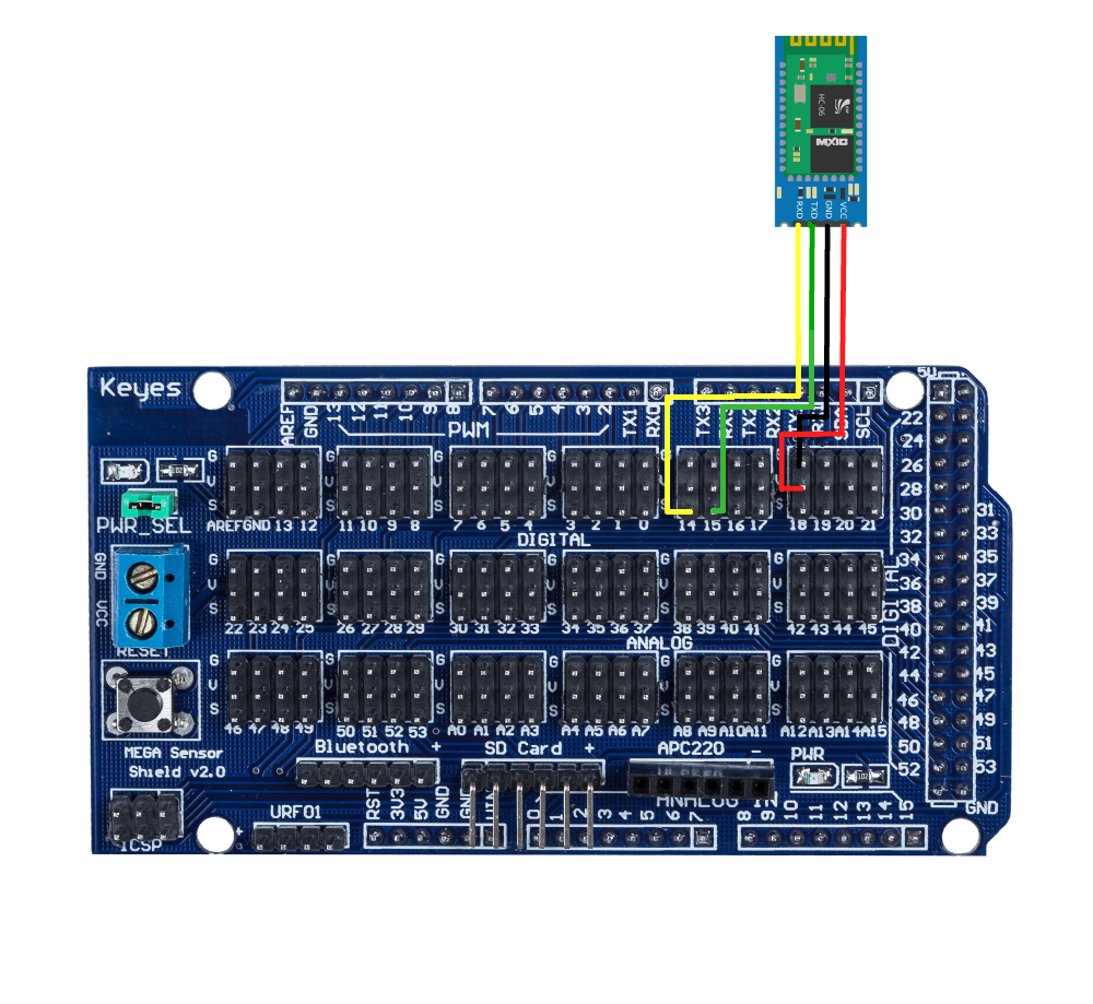
Arduino Mega Sensor Shield

Bluetooth Module

VCC

+5V / VCC

GND

GND

RX3

TXD

TX3

RXD

Power up the Arduino via USB, and you can see the Red LED on the Bluetooth module is blinking, which means the Bluetooth link is not established. Download this test code to the Mega. The code randomly generates numbers from 18 - 22 to simulate two temperature readings every 3 seconds. Once download complete, close the Arduino IDE, and now the Bluetooth can be tested in puTTY and our Serial Temp Monitor. 


Test in PUTTY

Open puTTY and enter the COM number the Bluetooth link. As can be seen below, mine is at COM4.
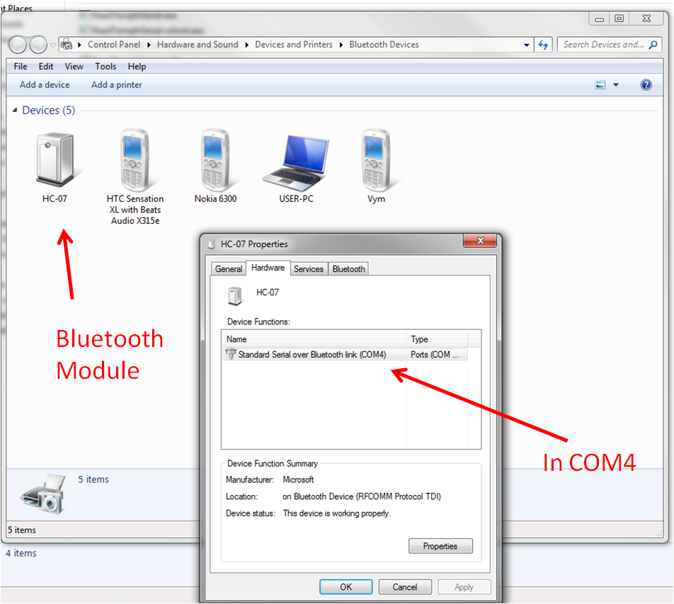
Bluetooh COM in Windows


Then connect the Bluetooth to puTTY with Baudrate = 9600
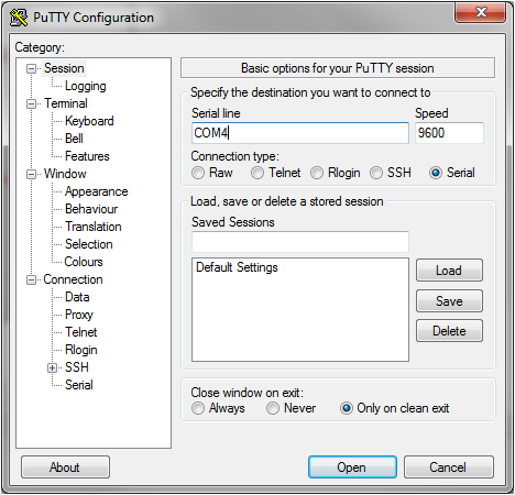
Connect Bluetooth to PUTTY

If the connection is established successfully, then you can see the LED on the Bluetooth module stays on. And in puTTY, you will receive strings like below.
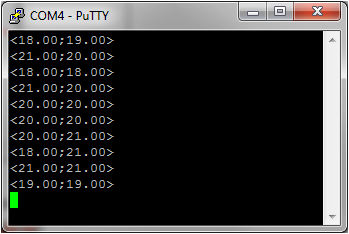
putty output


Test in Serial Temp Monitor

Download the executable SerialTempMonitor, and open it. Please make sure that the Bluetooth link is disconnected from puTTY, and the LED on the Bluetooth module is blinking.

Click on "Connect", after one moment, the temperature reading should appear.
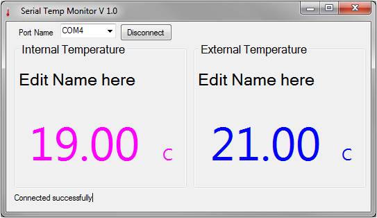
SerialTempMonitorDemo


If all working, congratulations, you are now ready to build a wireless temperature monitor. Finally, put all the components together, and load this code to your Mega, it should all work. The Serial Temp Monitor is an opened source C# program, developed by Hobbyist.
SerialTempMonitor Source Code Download

Interfacing Real Time Clock to Arduino Mega Sensor Shield

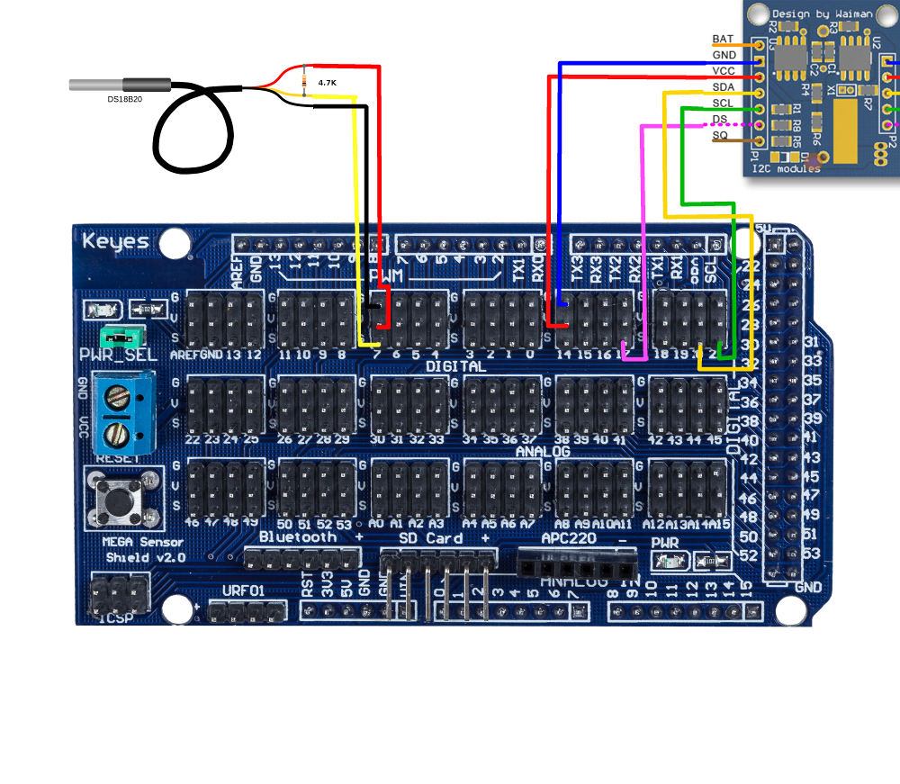
It’s time to fire up the Real Time Clock and the DS18B20 digital temperature sensor with the Arduino Mega. Remember that there is also a DS18B20 sensor on the RTC module, hence, this tutorial shows you how to interface two temperature sensors and a RTC with the Arduino Mega. The Mega Sensor shield reduces lots of pain while connecting the parts together, so it's highly recommended. Firstly of all, use the jumper wires to connect the circuit shown below (click to enlarge).


Arduino Mega Sensor Shield

RTC Module

DS18B20 Sensor

GND

GND


Signal 18

VCC


Signal 17

DS


Signal 20

SDA


Signal 21

SCL


GND


GND (black)

Signal 7


Signal (white)

Signal 6


VCC (red)


4.7k pull-up resistor between Signal and VCC


The external DS18B20 sensor requires a 4.7K pull-up resistor connecting between its VCC and Signal lines.

Now, download this RTClib, unzip it and put it to the Arduino libriary directory (C:\arduino-1.0.5\libraries). Restarting the Arduino IDE is required for the libriary to be installed properly. We are going to test the RTC and the Temperature sensor separately, this way it's easier to diagnose if there is any hardware problems.


RTC Testing

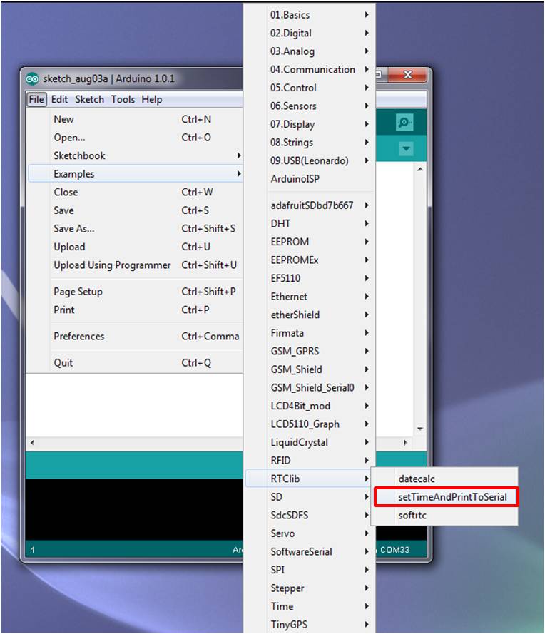
In Arduino IDE, navigate to File -> Examples -> RTClib -> setTimeAndPointToSerial

RTC example code

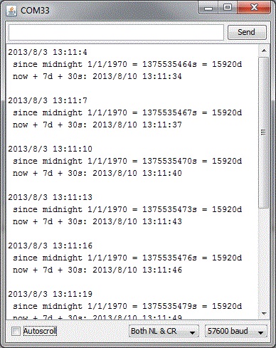
Download the example code to the Arduino (make sure the correct board and Serial COM are selected), and open Serial Monitor, and set the Baudrate to be 57600, if the RTC module is working, you should see someting like this. You may need to press the Reset button for the text to come out.

RTC Serial Results


Temperature Sensor Testing

There are two temperature sensors in the circuit, we call the one with a long wire and a steel cap as External sensor, and the one on the RTC module as Internal sensor.

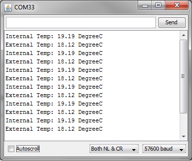
Download the OneWireLibrary and install it into the arduino IDE libraries folder and then load this code to Arduino Mega, and open Serial Monitor on Baudrate 57600. You should see the temperature reading like this. Again, you may need to press the Reset button for the text to come out.


Temp Reading Serial


If that's what you see, great, you have got the circuit working!

Interfacing SD Card Module to Arduino Mega Sensor Shield

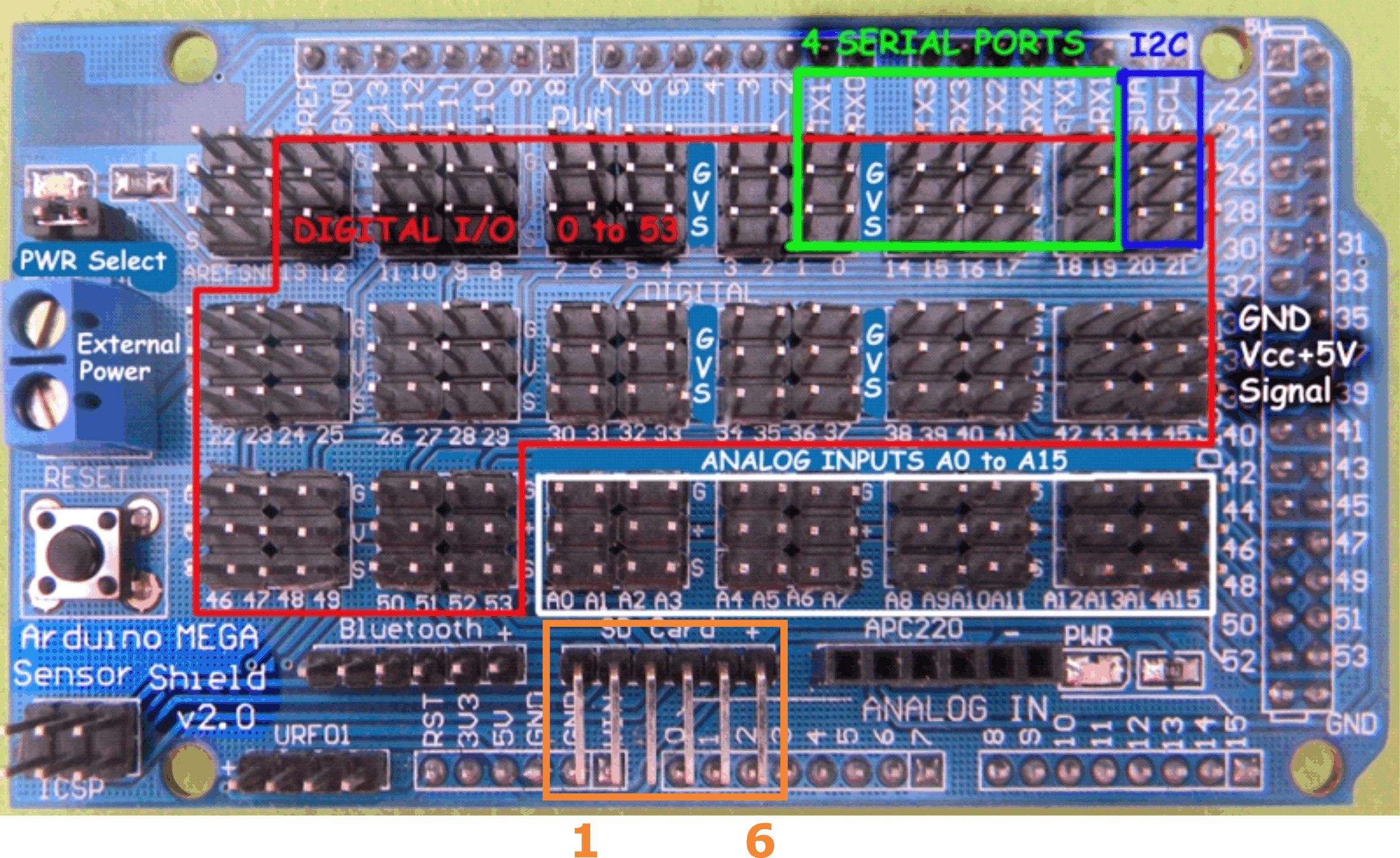
In this tutorial, you will learn how to interface the SD Card Module to the Arduino Mega via a Sensor Shield. Firstly, let's take a close look at the SD card connector on the Mega Sensor Shield.

Mega Sensor Shield SD Header Pinout

Mega Sensor Shield
SD Card Header

Corresponding
Arduino Mega Pins

Pin 1

50 MOSI

Pin 2

52 SCK

Pin 3

53 CS / SDCS

Pin 4

51 MOSI

Pin 5

GND

Pin 6

5V


The 6-pin SD Card connector is actually a SPI bus, and their pin designation is described in the table above.

Of course, the Mega Sensor Shield isn't essential to interfacing the SD Card module to the Arduino Mega, however, it absolutely makes life easier and adds reliability to your device.

There is one important reason why the Arduino Mega is chosen instead of the Arduino Uno (or any Arduino with the ATmega 328 microcontroller). There is only 2 KB of SRAM in the ATmega 328. SD card buffer requires 512 Byts, that's one quarter of the available memory. By putting a few Serial.print functions in the code, it's pretty easy to run out of SRAM in the ATmega 328 before you know it. As SRAM runs out, heap and stack clashes, and your program's behaviour can become strange and inconsistent. As confusing as it can get, it's hard to tell whether it's the 'bug' in the code or short of SRAM, a situation no one wants to go into. On the other hand, the Arduino Mega has 8 KB of SRAM, that's sufficient to most embedded programming, and plenty of room can be left for future improvement / extension.


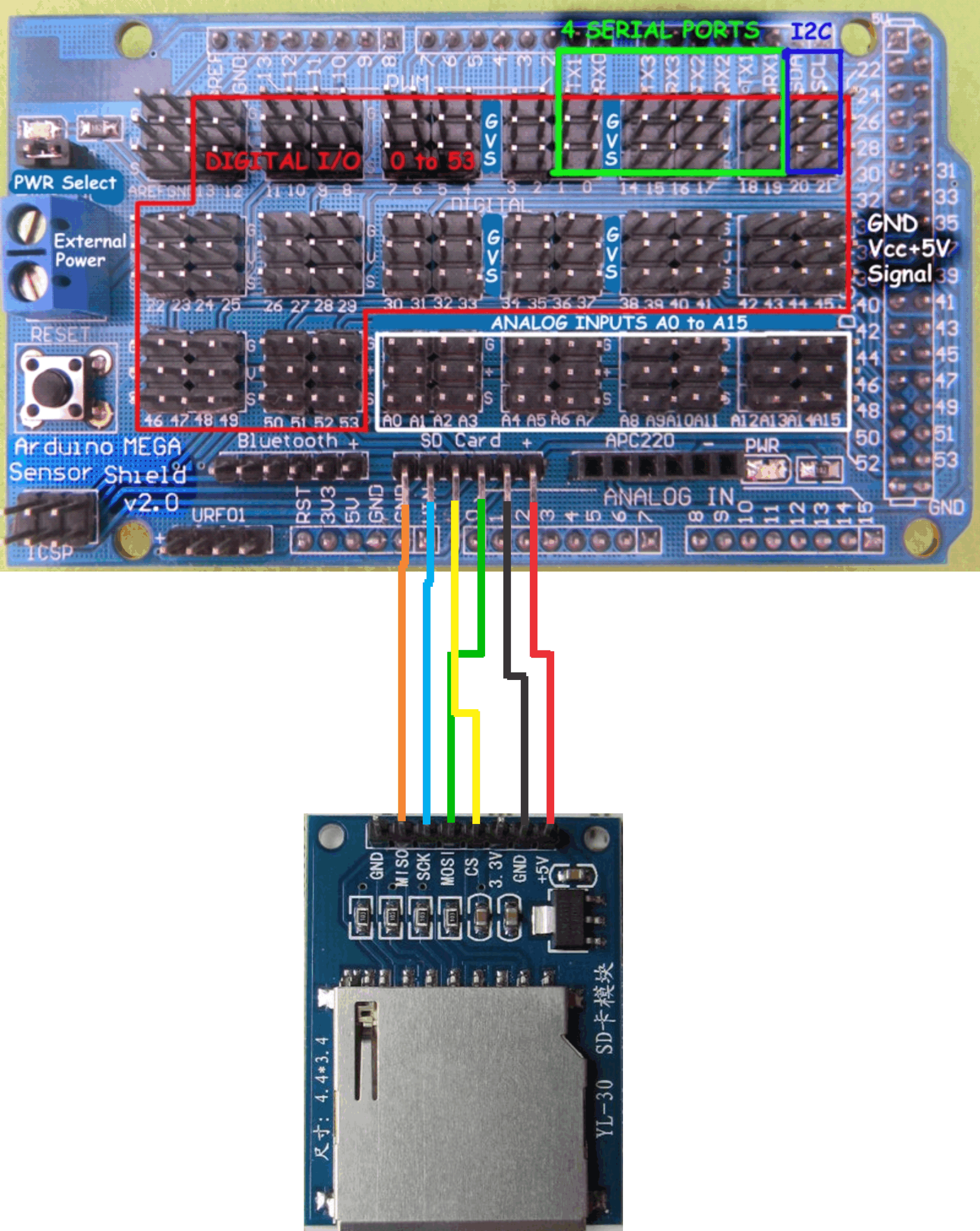
Interfacing SD card module to Mega Sensor Shield

Download this SD card library into the Arduino/libraries folder.

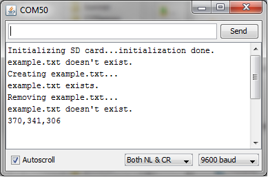
Once it's wired up, download this sketch to the Arduino Mega, make sure you have the correct board and serial com selected. Open the Serial Monitor, and set the Baudrate to 9600, if the SD card is working correctly, you should see something like this.

SD Connection successful

If it fails to initialize, try the things below:

1. Shut down Serial monitor, unplug the USB cable, wait for about 10 seconds (wait for the capacitors to discharge) , and plug it back again. Start Serial monitor, and push the reset button.

Zircon - This is a contributing Drupal Theme
WeebPal