Bluetooth

Interfacing Real Time Clock to Arduino Mega Sensor Shield

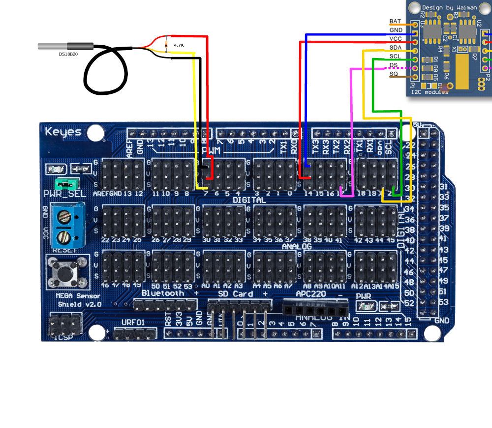
It’s time to fire up the Real Time Clock and the DS18B20 digital temperature sensor with the Arduino Mega. Remember that there is also a DS18B20 sensor on the RTC module, hence, this tutorial shows you how to interface two temperature sensors and a RTC with the Arduino Mega. The Mega Sensor shield reduces lots of pain while connecting the parts together, so it's highly recommended. Firstly of all, use the jumper wires to connect the circuit shown below (click to enlarge).


Arduino Mega Sensor Shield

RTC Module

DS18B20 Sensor

GND

GND


Signal 18

VCC


Signal 17

DS


Signal 20

SDA


Signal 21

SCL


GND


GND (black)

Signal 7


Signal (white)

Signal 6


VCC (red)


4.7k pull-up resistor between Signal and VCC


The external DS18B20 sensor requires a 4.7K pull-up resistor connecting between its VCC and Signal lines.

Now, download this RTClib, unzip it and put it to the Arduino libriary directory (C:\arduino-1.0.5\libraries). Restarting the Arduino IDE is required for the libriary to be installed properly. We are going to test the RTC and the Temperature sensor separately, this way it's easier to diagnose if there is any hardware problems.


RTC Testing

In Arduino IDE, navigate to File -> Examples -> RTClib -> setTimeAndPointToSerial

RTC example code

Download the example code to the Arduino (make sure the correct board and Serial COM are selected), and open Serial Monitor, and set the Baudrate to be 57600, if the RTC module is working, you should see someting like this. You may need to press the Reset button for the text to come out.

RTC Serial Results


Temperature Sensor Testing

There are two temperature sensors in the circuit, we call the one with a long wire and a steel cap as External sensor, and the one on the RTC module as Internal sensor.

Download the OneWireLibrary and install it into the arduino IDE libraries folder and then load this code to Arduino Mega, and open Serial Monitor on Baudrate 57600. You should see the temperature reading like this. Again, you may need to press the Reset button for the text to come out.


Temp Reading Serial


If that's what you see, great, you have got the circuit working!

Terminator

The Terminator is a low cost and easy to use robotic kit, it includes:

  • Terminator chassis
  • Dual channel motor controller
  • Arduino Duemilanove
  • USB cable
  • AA x 4 battery case
  • some wires for connections

No soldering is required!!

The Terminator shown in the photos here uses the Arduino Demilanove ( Can be replaced with Uno with no change in functionality or code )


The pin out of the motor controller is depicted in the photo below


Blu-tack is used to fix the electronics on the chassis.

Ok, now it's time to wire the electronics up..First of all, connect the battery case to the Acc (red) and GND (black) of the controller. Then, use the provided wires, connect the controller to the Arduino according to the table below


Motor controller Arduino
5 V 5 V
GND GND
1 Pin 5
2 Pin 6
3 Pin 9
4 Pin 10

Note: the reason why the Arduino pin 5,6,9,10 are chosen is because they all support PWM, which is needed for motor speed control using analogWrite() in the code.

Note that the GND of the controller needs to be shared with the Arduino and the battery case. Photo below shows the controller signals and power pins being connected to the Arduino.

For testing, no battery is needed, or the battery case can be left at the OFF position. Plug the Arduino to the PC via a USB cable, and down load this example code to the Arduino. Switch on the serial monitor, and send the key 'e', and press enter, the Terminator should be turning..Play with the code and change anything you want. It is much easier to control the Terminator using the puTTY serial com interface instead of the Arduino Serial monitor, because in puTTY you don't need to press the enter key every  time you send a command.


How to make the Terminator go wireless ?

To make the Terminator go wireless, all you need is a Bluetooth module,

No modification is needed for the Arduino code. Since the Arduino only receives and sends data through its serial port, it doesn't even know and doesn't care whether the serial port is a Bluetooth or a cable connecting directly to the computer. Photo above shows a wireless Terminator. The LED on the Bluetooth stays on indicting the wireless connection has been established.

The Terminator is ready for action!!  There is a detailed tutorial on how to connect the Bluetooth module to the Arduino, See that for more details to interface the Bluetooth Module.

Giving life to the Robot

Once the Bluetooth is tested and working and you have the motors wired and ready to go,

The  Robo is ready to go wireless. This is a tutorial details how we go about it.

Connect the blue tooth to the Arduino board:

Before connecting the Bluetooth to the Arduino, you need to shutdown the Arduino IDE program (the program you use to write upload code to the Arduino). This is because the serial interface of the Arduino may not be shared between the Bluetooth and the PC at the same time, otherwise the Arduino IDE may crash. Or you can run into this Slow Arduino IDE problem if your Bluetooth is on. Connect the tx of the blue tooth module to the rx (pin0) on the Arduino board and the rx to the tx (pin1) as described in the table below.

Bluetooth Arduino
Vcc 3.3V
GND GND
TXD RXD
RXD TXD

Once open up puTTY, and select the correct COM port, the blue tooth module’s LED should be changed from flashing to stays on, which indicates the connection is established. Now it's time to have some fun, key in 'e', 'c', 's', 'f', 'd' in puTTY to control your Rover!


Sprinkle some life into the ROBOT!!!


Get yourself this cool Robot!!

 tags: robotics, robot games, make a robot, build a robot, kid robot, mr robot, create a robot, robot wars

Zircon - This is a contributing Drupal Theme
WeebPal