dancing lights

Step 1: Making the LED lights dance to your music

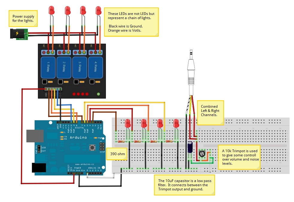
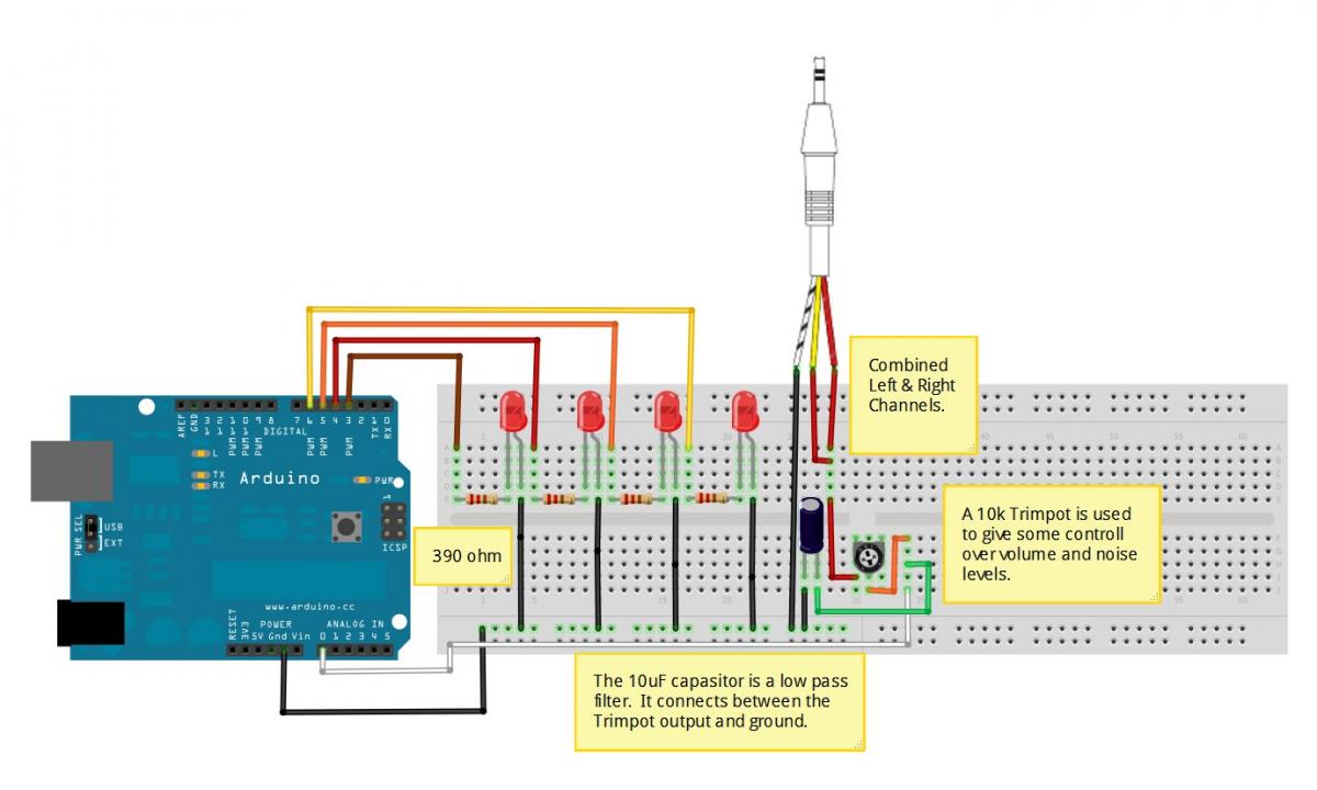
Objective here is to use the A/D converter on Arduino to read input sound and light up a set LEDs to reflect the level of the sounds volume. The LEDs are controlled from Digital pins 3, 4, 5,6.  They are turned on based on what the level of input is from the Analog 0 pin, which is connected to the headphone jack.


Parts:

1x Arduino

4x LEDs

4x 390 ohm resistors

1x 10k trimpot

1x Headphone jack

1x 10uF Capacitor


Step one layout


// LED light dance


#define soundpin A0               //  reads the power from the light sensor from Analog input 0

#define LED1 3                    //  4 Leds LED's on Digital output pins 3,4,5,6

#define LED2 4

#define LED3 5

#define LED4 6


int sound;


void setup()

{

  // initialize the serial communications:

  Serial.begin(9600);


  // Provide power by using the analog inputs as normal digital pins.  

  pinMode(soundpin, INPUT);

  pinMode(LED1, OUTPUT);

  pinMode(LED2, OUTPUT);

  pinMode(LED3, OUTPUT);

  pinMode(LED4, OUTPUT);

}

void loop()

{

      sound=analogRead(soundpin);   // this samples the sound constantly

      if((sound)>200)

        {

             digitalWrite(LED1,HIGH);   // set the LEDs on

             digitalWrite(LED2,HIGH);

             digitalWrite(LED3,HIGH);

             digitalWrite(LED4,HIGH);

        }  

        else if((sound)>150)

        {

             digitalWrite(LED1,HIGH);   // set the LED on

             digitalWrite(LED2,HIGH);

             digitalWrite(LED3,HIGH);

             digitalWrite(LED4,LOW);   // set the LED off

        }

        else if(sound>100)

        {

             digitalWrite(LED1,HIGH);   // set the LED on

             digitalWrite(LED2,HIGH);

             digitalWrite(LED3,LOW);   // set the LED off

             digitalWrite(LED4,LOW);

        }

         else if(sound>50)

        {

             digitalWrite(LED1,HIGH);   // set the LED on

             digitalWrite(LED2,LOW);   // set the LED off

             digitalWrite(LED3,LOW);

             digitalWrite(LED4,LOW);

        }

         else

        {

             digitalWrite(LED1,LOW);   // set the LEDs off

             digitalWrite(LED2,LOW);

             digitalWrite(LED3,LOW);

             digitalWrite(LED4,LOW);

        }


     Serial.println(soundpin);              //output for serial monitor


     delay(25);                                   // And a shot delay

}


Links to projects that helped with getting this project working.

http://www.instructables.com/id/VU-Meter/ 

http://arduinoarts.com/2011/08/uv-meter/
 

Step 3: Weaving the relay modules with the dancing lights


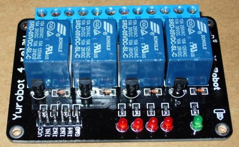
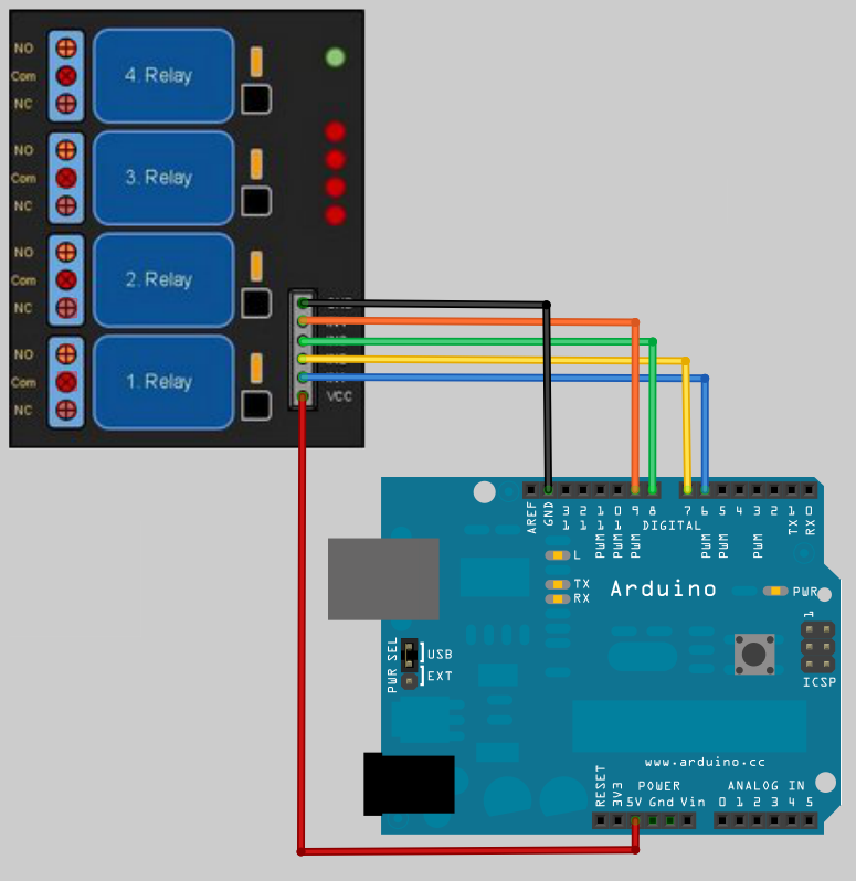
To connect the 4 Relay board to an Arduino is very easy.  

You only need to connect the Arduino +5v to the 4 Relay board VCC pin and an Arduino Ground to the 4 Relay board GND pin.


Then it’s a matter of just connecting some data pins from the Arduino to the 4 Relay board IN pins.


In the example code below I used Arduino pins 7, 8 , 9, 10.

I didn’t use the same digital pins as the LEDs because they are inversed to each other.  

The LEDs get power from the Arduino, that means when the digital pin is HIGH (1) it has +5v on the line and the LED lights up.

The relay commands are the opposite to this and the relay is switched with the IN pin is set LOW (0).


The relays default state is to connect COM to NC (normally closed), this is also done by setting the relays IN pin HIGH.  

This is a safety feature in-case you Arduino looses power it turns off all the relay switches.  

To change the relays state so NO (Normally Open) the pin is set to LOW.


I have some 12v DC lights that I want to activate like LEDs as a VU meter.

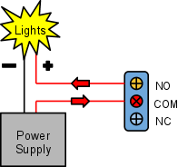
To do that I connect the lights power line to the 4 Relay board relay Com connector and

the line to the lights connects to the relays NO connector.  The NC connect is left empty.


Example of connecting Lights to the relays.


Code: Available with purchase


Other Details:

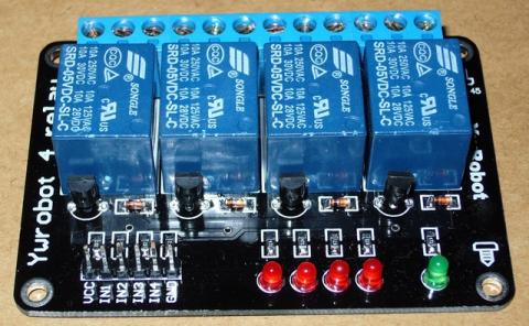
Specification of 4 Relay board:

Equipped with high-current relay, AC250V 10A ; DC30V 10A

Support 5V voltage

Independent wiring in contact area , safe and reliable

Standard interface that can be expanded in a variety of development boards

Equipped with screw holes for easy installation

Applicable to a variety of platforms including   Arduino / AVR / ARM

Size: 7 X 4.9 X1.8 (high) cm


Schematic Diagram:


More information about relays: http://www.kpsec.freeuk.com/components/relay.htm


Tips on working with AC power:   … IT IS DANGEROUS !!!...    

Only work with AC if you really know what your doing, it can kill.


Step 2: Interfacing the relay modules to the Arduino

Relays work on electromagnetism, When the Relay coil is energized it acts like a magnet and changes the position of a switch. The circuit which powers the coil is completely isolated from the part which switches ON/OFF, This provides electrical isolation. This is the reason we can control a relay using 5V's from an arduino and the other end of it could be running an 230V appliance, the 230V end is completely isolated from the 5V arduino circuitry.


To connect the 4 Relay board to an Arduino is very easy and allows you to turn on and off an wide range of devices, both AC and DC. The first to connections are the ground and power pins,  You need to connect the Arduino +5v to the 4 Relay board VCC pin and the Arduino ground to the 4 Relay board GND pin.  Then it’s a only a matter of just connecting the communication pins, labeled IN1, IN2, IN3 and IN4, two 4 data pinson the Arduino.In the example code below we used Arduino pins 7, 8 , 9, 10.  Its a good idea to avoid using Data pins 0 and 1 as they are used by the Arduino for serial communication and can cause problems when uploading code to the Arduino.


The default state of the relay when the power is off for COMM (power) to be connected to NC (normally closed), this is the equivalent of setting the 4 Relay boards IN pin to HIGH (has +5v sent to it)  It is a safety feature to notuse the NC connector in-case you Arduino looses power it will automatically turns off all the devices connected to the relay.  When you have something connected to the relays NO (Normally Open) connector and you set the corresponding IN pin to LOW (0v), power will flow in from the COMM connector and out of the NO connectorpowering your device..


Above: Example of connecting power and lights to a relays COM and NO connectors.  

Below: Connecting to the Arduino.


// Basic 4 Realy board connection

// Each relay is turned on for 2 seconds and then off.

// You can here them click as there state changes from off to on and on to

// off.

// You will also see the corresponding Red LED on the 4 Relay board

// light up when the relay is on.


 //  define names for the 4 Digital pins On the Arduino   

// These data pins link to 4 Relay board pins IN1, IN2, IN3,

IN4

#define RELAY1  6                        

#define RELAY2  7                        

#define RELAY3  8                        

#define RELAY4  9


void setup()

{    

// Initialise the Arduino data pins for OUTPUT

  pinMode(RELAY1, OUTPUT);       

  pinMode(RELAY2, OUTPUT);

  pinMode(RELAY3, OUTPUT);

  pinMode(RELAY4, OUTPUT);

}


 void loop()

{

   digitalWrite(RELAY1,LOW);           // Turns ON Relays 1

   delay(2000);                                      // Wait 2 seconds

   digitalWrite(RELAY1,HIGH);          // Turns Relay Off


   digitalWrite(RELAY2,LOW);           // Turns ON Relays 2

   delay(2000);                                      // Wait 2 seconds

   digitalWrite(RELAY2,HIGH);          // Turns Relay Off


   digitalWrite(RELAY3,LOW);           // Turns ON Relays 3

   delay(2000);                                      // Wait 2 seconds

   digitalWrite(RELAY3,HIGH);          // Turns Relay Off


   digitalWrite(RELAY4,LOW);           // Turns ON Relays 4

   delay(2000);                                      // Wait 2 seconds

   digitalWrite(RELAY4,HIGH);          // Turns Relay Off        

 }


Previous Step: Making LED lights dance to your music

Next Step: Music Plays and lights dance

Zircon - This is a contributing Drupal Theme
WeebPal